Getting a CAD model built sounds straightforward until the first revision lands with wrong dimensions or a geometry that doesn’t match what you pictured. Most of these problems trace back to one cause: the client didn’t know what to send a CAD designer before starting. The information you hand over in that first message decides whether the project runs cleanly or loops through correction cycles that cost everyone time and money.
Why the Brief Determines Everything
A SolidWorks designer works from whatever you give them. Hand over a vague description and one blurry photo, and the result will be a model built on assumptions — and every assumption is a revision waiting to happen. Send clear, complete information upfront, and the designer can focus entirely on engineering the geometry correctly instead of guessing at intent. First-pass accuracy is almost entirely determined by the quality of that initial handover, not the complexity of the part.
What to Send a CAD Designer Before Starting: Sketches and References
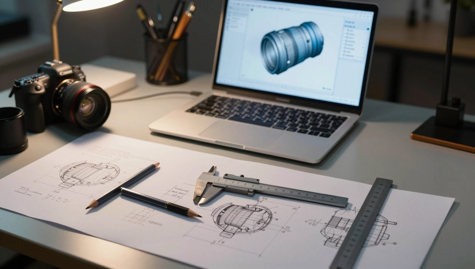
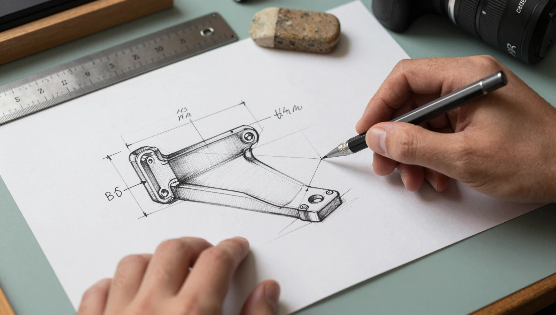
Sketches are the most universally useful thing you can provide, and they do not need to be neat. The point is to communicate design intent, not artistic quality. Use multiple views — front, side, and top at minimum. Label every feature that matters. Show the overall envelope and call out critical dimensions directly on the drawing. A ruler or coin placed next to a photo for scale reference is worth more than a written paragraph describing the size.
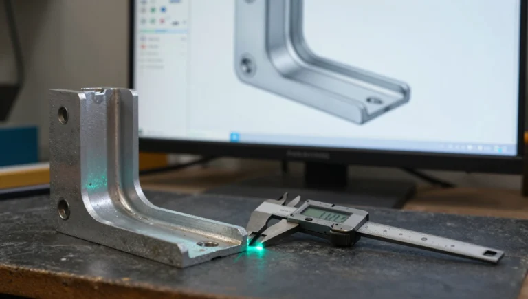
If the part already exists in some form — a competitor product, a rough physical prototype, or a legacy part you are redesigning — photograph it from multiple angles with something known for scale. If you are redesigning an existing component and have the original file, send it. The designer can work from it directly or use it as a dimensional reference rather than reconstructing geometry from scratch. Include photos of any adjacent parts or assembly context too, even if those parts are outside the modeling scope.
Dimensions and Critical Measurements
This is where most briefs fall short. Sketches without dimensions force guesswork, and guesswork becomes revision rounds. For every part, provide the following:
Overall envelope: maximum length, width, and height. Even approximate values help — “roughly 80 mm × 40 mm × 15 mm” tells the designer what scale they’re working at before any features are placed.
Feature-level dimensions: hole diameters, wall thickness targets, fillet radii, thread specifications (M3, M4, ¼-20 — coarse or fine pitch), chamfer angles, and boss heights. Include units throughout and stick to one system — millimeters or inches — for the entire brief. Flag which dimensions are hard constraints and which are approximate. A mounting hole pattern that must match an existing PCB is fixed. The fillet radius on a cosmetic corner is flexible. Making this distinction saves the designer from over-tolerancing features that don’t require it — and from under-tolerancing the ones that do.
Tolerances and Fit Requirements
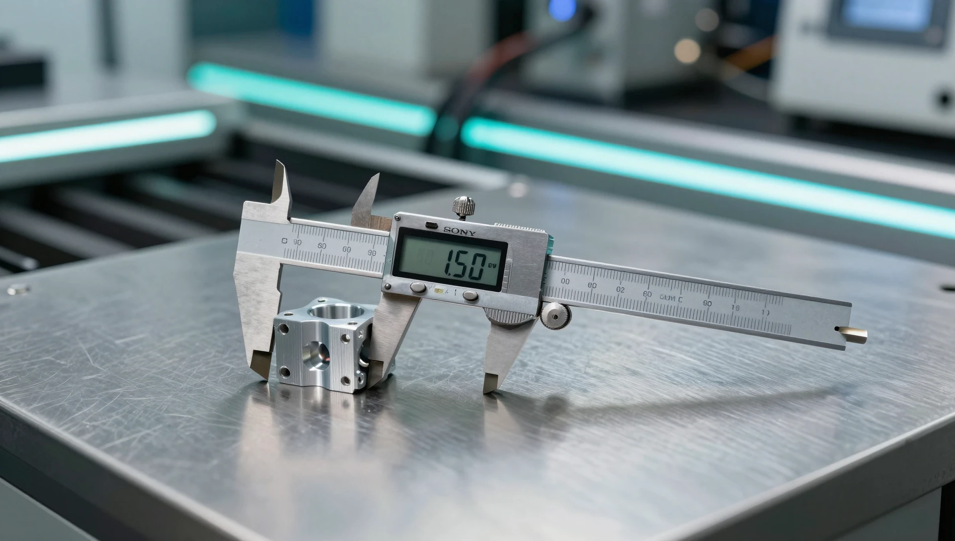
Not every feature needs a tight tolerance, but the ones that do must be stated explicitly. Standard FDM 3D printing holds approximately ±0.3 mm on most consumer-grade printers. Machined aluminum can hold ±0.05 mm and tighter. If two parts must mate, slide together, or press fit, state the intended fit class and the nominal diameter.
For assemblies with mating parts, specify whether you need a clearance fit for assembly ease, a transition fit for light location, or an interference fit for a permanent joint. A 10 mm hole designed for a 10 mm shaft behaves completely differently depending on the required joint. If you are working from ISO tolerance standards, reference the fit designation directly — the designer will apply the correct deviation without further back-and-forth. If you have no tolerance spec at all, say so; the designer will apply standard engineering practice for the manufacturing method.
Material, Finish, and Manufacturing Intent
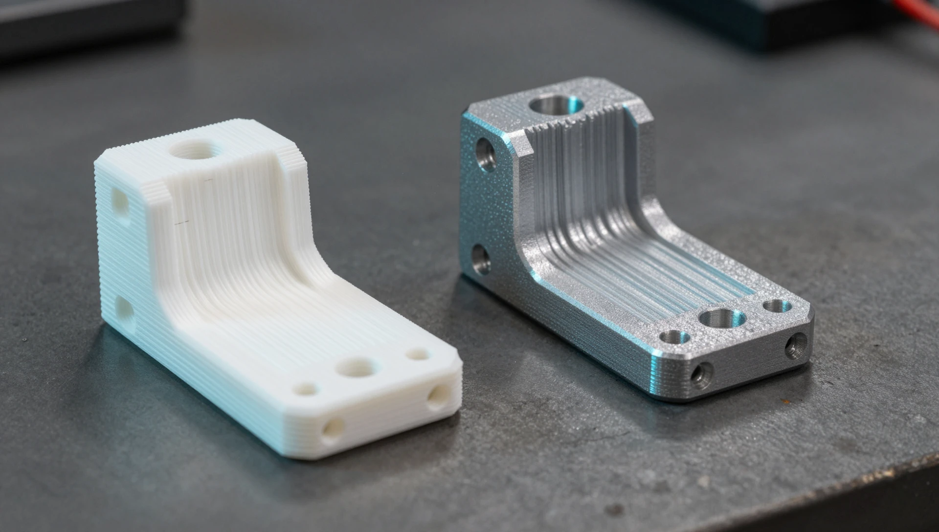
The same geometry is modeled differently depending on whether it will be 3D printed in PETG, injection molded in ABS, or machined from 6061 aluminum. Material choice drives wall thickness minimums, draft angles for molding, rib and boss design, and how features are positioned relative to the parting line. State the intended material and manufacturing process at the start of the brief.
If you are unsure about material, describe the functional requirements instead: “must support 8 kg without deflecting” or “exposure to outdoor UV and temperatures up to 70°C.” That gives the designer enough to make a competent recommendation before modeling begins. Our SolidWorks modeling service covers single prototype parts through production-ready assemblies, and clarifying material intent at the brief stage prevents expensive geometry changes downstream.
How to Write a Clear CAD Design Brief
A solid cad design brief fits on one page for most projects. The sections that matter are: the purpose of the part, the intended manufacturing process, the mating parts and assembly context, the critical dimensions and hard constraints, and the required output formats. A clear paragraph under each heading is enough — you do not need to write a formal engineering specification.
Describe what the part does before you describe what it looks like. “This bracket clamps a 22 mm OD pipe to a flat vertical surface and must not flex under 15 N of lateral load” tells the designer how to structure the geometry for function. “I want a U-shaped bracket” tells them almost nothing about structural requirements.
Understanding how to brief a cad designer is less about formal paperwork and more about the right inputs in the right order. State the output file format upfront: STEP for machining or tooling, STL for direct 3D printing, SLDPRT source for future editing, or a dimensioned drawing PDF for fabrication. Output format affects how the model is structured internally, and changing the requirement after modeling is complete often means rework.
Output Formats and Delivery Requirements
Setting clear cad project requirements at the start prevents scope confusion at delivery. STL works for most direct-print jobs. STEP is the universal format for machining, sheet metal, and injection mold tooling. SLDPRT gives you editable SolidWorks source. If you need GD&T callouts and a dimensioned technical drawing, flag it in the brief — it adds time and should be scoped and priced before modeling begins.
Clients who prepare files for cad designer review with complete dimensions and clear intent typically resolve projects in a single revision round. Clients who start without measurements often reach three or four rounds before the model matches the vision. The gap is almost entirely in the quality of the initial brief, not in part complexity. When in doubt about output format, ask your manufacturer or printer before you place the order — they will tell you exactly which format their toolpath requires.
We have completed 7,000+ projects across 40+ countries, with a 4.9★ rating from 4,470+ verified clients and 24-hour delivery on most parts. Send us your brief — however rough it is — and we will tell you exactly what else we need to move forward. Contact us directly at contact@minicad.io.