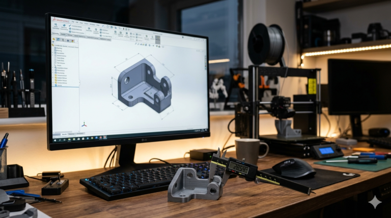
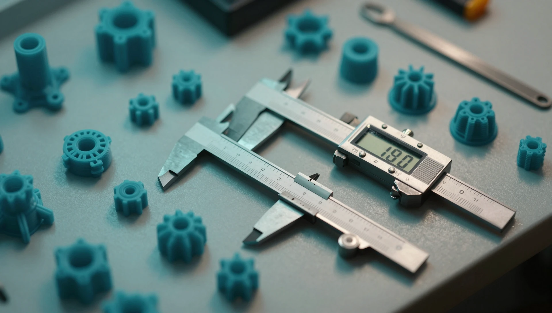
Two parts printed exactly to nominal dimension. They bind on assembly. You sand them, reprint, repeat. Most engineers hit this problem on their first 3D-printed mechanism, and the fix is simpler than a reprint: correct tolerances and clearances for 3D printing need to be built into the CAD model before you slice. This guide gives you the numbers that work — clearance values for sliding fits, locating fits, and press fits, plus the snap fit geometry rules that actually survive repeated cycling.
Why FDM Parts Never Match Nominal Dimension
FDM extrudes molten filament that spreads slightly as it contacts the previous layer. A perimeter bead drawn at 0.4 mm width typically measures 0.5–0.6 mm once cooled, because the nozzle pushes material outward against the existing surface. That extrusion spread affects every external wall: a 20 mm cube designed in SolidWorks commonly prints at 20.2–20.4 mm on a well-tuned desktop printer.
Z-axis accuracy has a different error source — layer stepping. At 0.2 mm layer height, a 1.5 mm feature rounds to 7 or 8 layers (1.4 or 1.6 mm). For mating surfaces loaded in the vertical direction, design to a multiple of your layer height to guarantee you land in the right direction.
Material shrinkage adds a third variable. PLA contracts about 0.3% on cooling. PETG contracts 0.4–0.5% and stays flat. ABS contracts 0.5–1.5% and warps, making dimensional accuracy genuinely unpredictable without an enclosure. These three sources — extrusion spread, layer stepping, and shrinkage — stack. Correct tolerances account for all of them.
Three Clearance Types for 3D Printed Assemblies
Every mating interface falls into one of three categories. Match the category before picking the number.
A clearance fit means one part moves freely inside or over another with no resistance — a lid over a box, a shaft in a bearing bore, a drawer in its housing. You need a visible gap in the model; the fit feels loose when separated but does not rattle in use.
A locating fit (transition fit) means one part drops into another without play but without requiring force — a PCB in a recess, a panel in a frame. Gravity and friction hold it; no fastener or snap needed.
An interference fit (press fit) means one part must be forced into another. The surrounding material compresses elastically around the intruding part and grips it. In FDM this works — within tight limits — because printed walls deform slightly rather than fracturing, provided wall thickness is sufficient.
Tolerances and Clearances for 3D Printing — The Number Reference
These values work for calibrated FDM at 0.2 mm layer height in PLA or PETG. All measurements are per side — the gap added to each mating surface. For a 10 mm pin in a bore, “0.3 mm clearance per side” means the bore diameter is 10.6 mm.
For a free sliding fit (lids, linear slides, rotating shafts in non-precision use): 0.3–0.5 mm per side. For a running fit (continuous rotation, faster speeds): 0.4–0.6 mm per side. For a locating fit with no play: 0.1–0.2 mm per side — the part seats firmly and stays put without snapping. For a light press fit held without additional fasteners but removable with effort: 0.05–0.1 mm interference. For a permanent press fit (destructive to separate): 0.1–0.15 mm interference.
For ABS, add 0.1 mm to all clearance values — shrinkage and warp create extra dimensional uncertainty. For resin (SLA/MSLA), tighten all values by 0.05–0.1 mm; resin holds tolerances of ±0.05 mm versus ±0.2–0.3 mm for FDM and accepts tighter fits cleanly. When sending geometry to a fabrication partner or STL file design service, make sure the clearances are modeled into the file — a correct STL encodes the geometry, not the intent.
Press Fit 3D Printed Parts — What Holds and What Splits
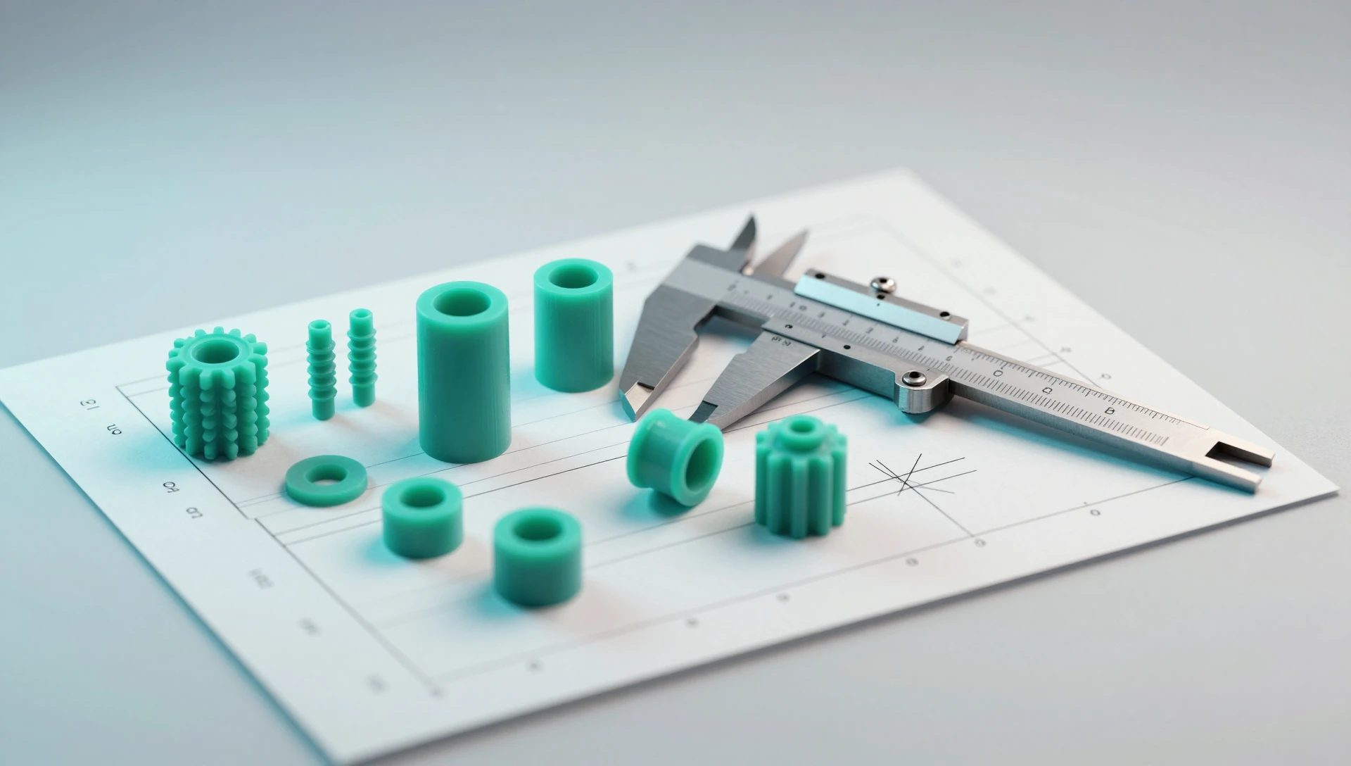
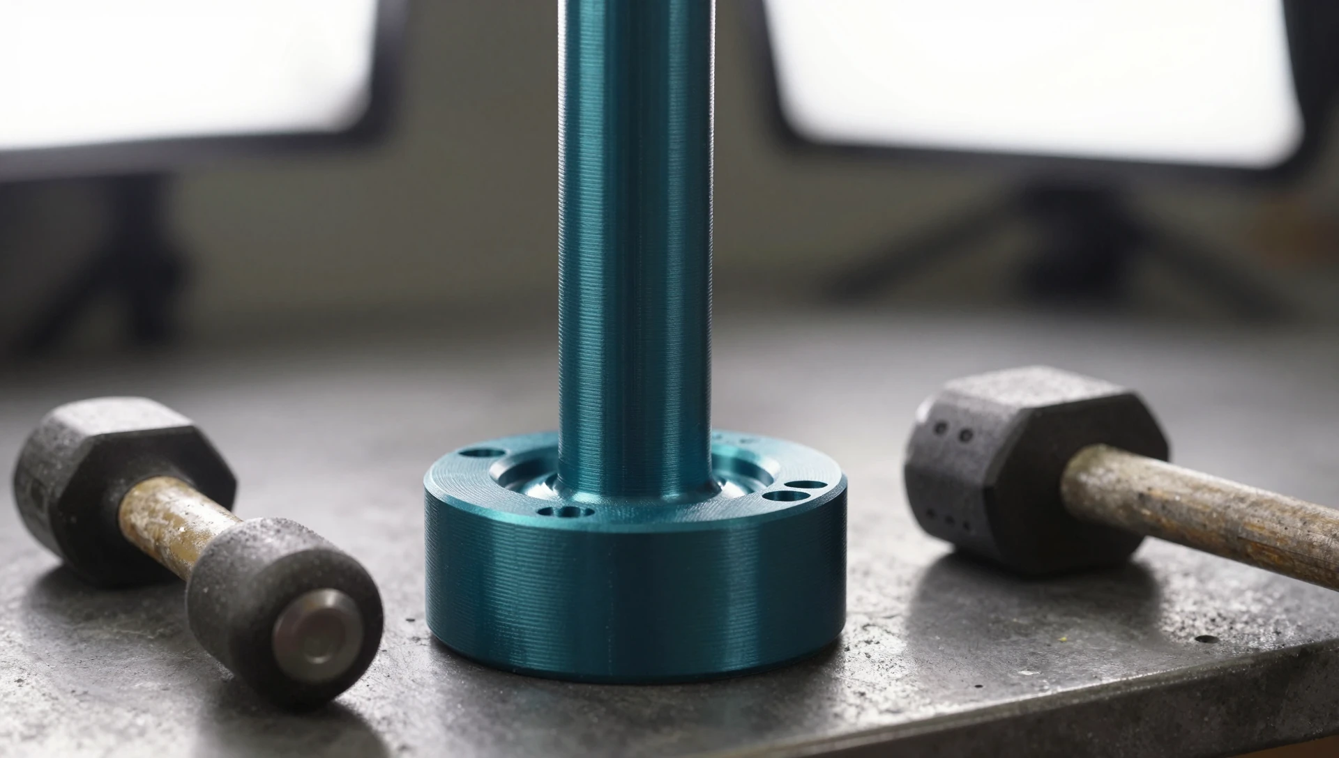
FDM press fits succeed when the wall surrounding the bore is thick enough to deform elastically rather than crack. The failure mode is consistent: force applied to insert a shaft loads the bore wall in hoop tension, and if wall thickness is under 2.5 mm, the bore splits along a layer line before the parts fully seat.
Practical rules for FDM press fits: keep bore-wall thickness at 3 mm minimum. Use 0.05–0.1 mm interference for joints you may need to disassemble; 0.1–0.15 mm for permanent joints. Always chamfer the bore entry at 0.5–1 mm and the pin tip at the same angle — this guides entry and prevents the bore edge from acting as a crack initiator. Tap in with a mallet on a flat block rather than pressing by hand; distributed force prevents corner splitting.
PETG outperforms PLA in press fits because its elongation at break (~200%) far exceeds PLA’s (~6%). It stretches slightly on interference insertion instead of fracturing. ABS is acceptable where heat resistance matters. For high-cycle press fit joints assembled and disassembled repeatedly, design in a brass heat-set insert on the bore side — the insert provides metal-on-plastic interference that is repeatable and durable across hundreds of insertions.
Snap Fit 3D Printing — Design Rules That Prevent Failure
A snap fit is a cantilever beam that deflects during insertion and springs back behind a retention ledge. It is tool-free and elegant — but FDM snap fits fail far more often than injection-molded ones. The reason is anisotropy: printed layer bonds carry only 40–60% of the strength of in-layer bonds, and a snap fit beam loaded across layer lines bends through its weakest cross-section.
The single most important rule: orient the snap fit beam parallel to the build plate. If the beam deflects in XY, it bends along strong in-layer bonds and can survive hundreds of cycles. If it deflects in Z, it typically breaks after 5–20 cycles in PLA. Redesigning the print orientation costs nothing; reprinting failed snap fits costs time and material.
Strain is the other limiter. For PLA, keep beam strain below 2%; for PETG, below 4%. Snap fit strain = 1.5 × (t² × δ) / L², where t is beam thickness, δ is deflection, and L is beam length. For a 12 mm-long, 1.5 mm-thick PETG beam deflecting 1.5 mm: strain = 1.5 × (2.25 × 1.5) / 144 = 3.5% — inside the PETG limit. The same geometry in PLA exceeds the 2% threshold and will fatigue quickly. According to Xometry’s manufacturing resources, FDM snap fits in standard materials should target 2% strain maximum for reliable long-term cycling. Size the beam length accordingly before modeling.
Calibrate Before the Assembly Print
Every value in this guide assumes a calibrated printer. An off-calibration machine shifts all numbers unpredictably, and “my clearance fit binds even at 0.5 mm per side” is almost always a calibration miss, not a tolerance error.
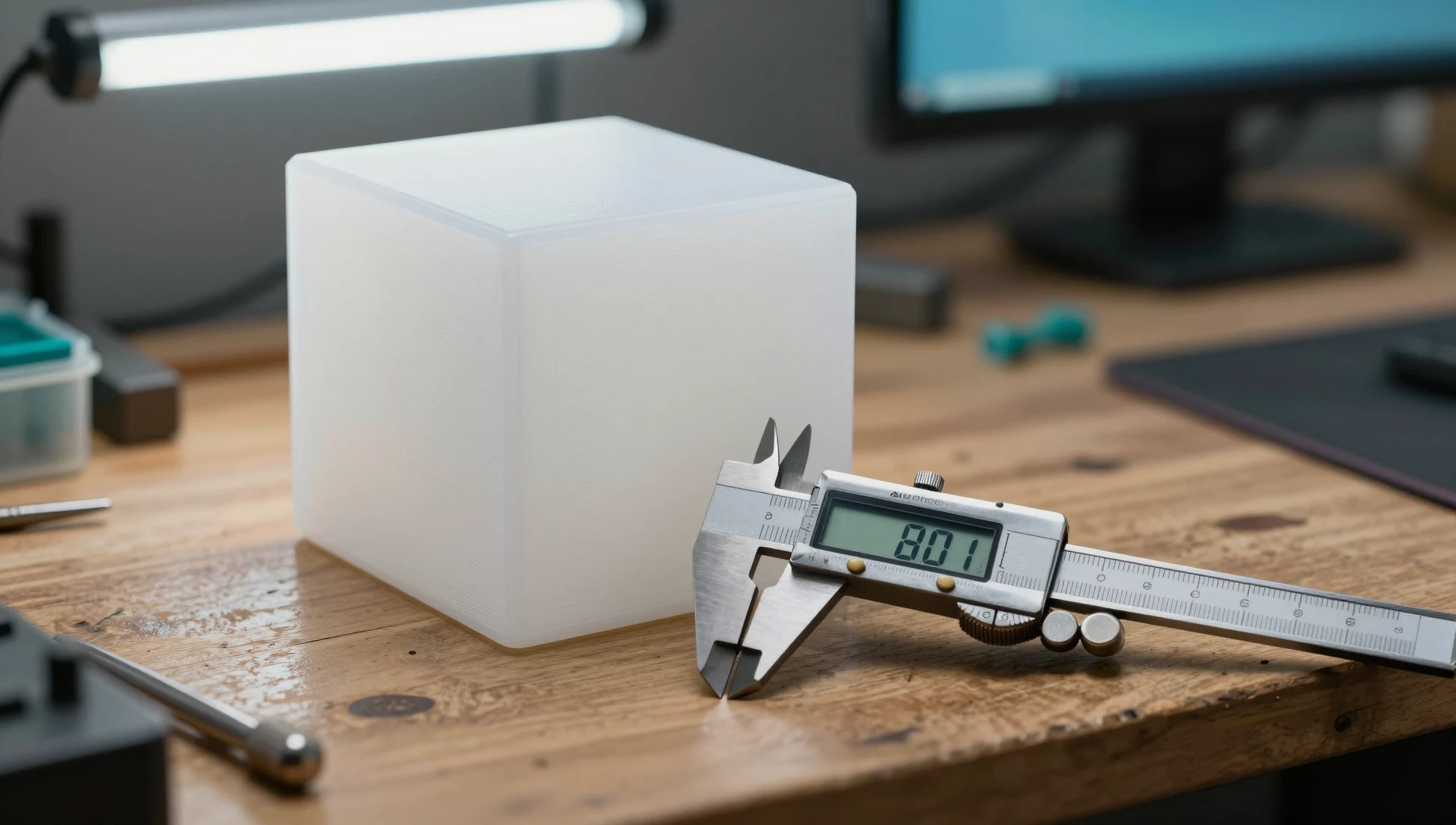
Print a 20 × 20 × 20 mm calibration cube before cutting assembly geometry. Measure all six faces with a caliper. If X and Y read more than 0.15 mm from 20 mm, set Horizontal Expansion (Cura) or XY Size Compensation (PrusaSlicer) to the negative of the measured error — typically −0.1 to −0.2 mm. Re-print and verify before proceeding.
Then run a fit test: print five short pin-in-hole samples at 0.1, 0.2, 0.3, 0.4, and 0.5 mm clearance per side. Find the tightest value that slides without binding. Use that number for sliding fits in this design, on this printer, with this filament brand — because filament diameter variation between brands shifts results by 0.05–0.1 mm on its own. For designs involving multiple parts where 3D print clearance between parts is critical, this test is not optional; it is the fastest way to confirm your machine’s actual offset before committing material to a full run. Our companion guide on 3D printing design rules covers wall thickness, overhang limits, and bridging specs that work alongside these tolerance values.
Over 7,000+ projects we have seen more assembly failures from skipped calibration than from wrong tolerance values. Verify the machine first, then trust the numbers.
When your assembly needs to be right on the first print, MiniCAD models every mating interface with explicit clearances in SolidWorks — sliding fits, locating fits, press fits, and snap fits built in before the file leaves our hands. 7,000+ projects · 40+ countries · 4.9★ (4,470+ reviews) · 24-hour delivery. Request a quote or email contact@minicad.io.