Support structures for FDM 3D printing are a silent cost multiplier that most clients never see until they get their first quote revision. A part designed without thinking about overhangs can add 40% to print time, consume a third more filament, and deliver surface quality that requires significant post-processing on functional faces. Whether you are designing your own part or working with a CAD service, understanding when supports are necessary — and how to avoid them — saves money on every production run.
Why Support Structures for FDM 3D Printing Matter
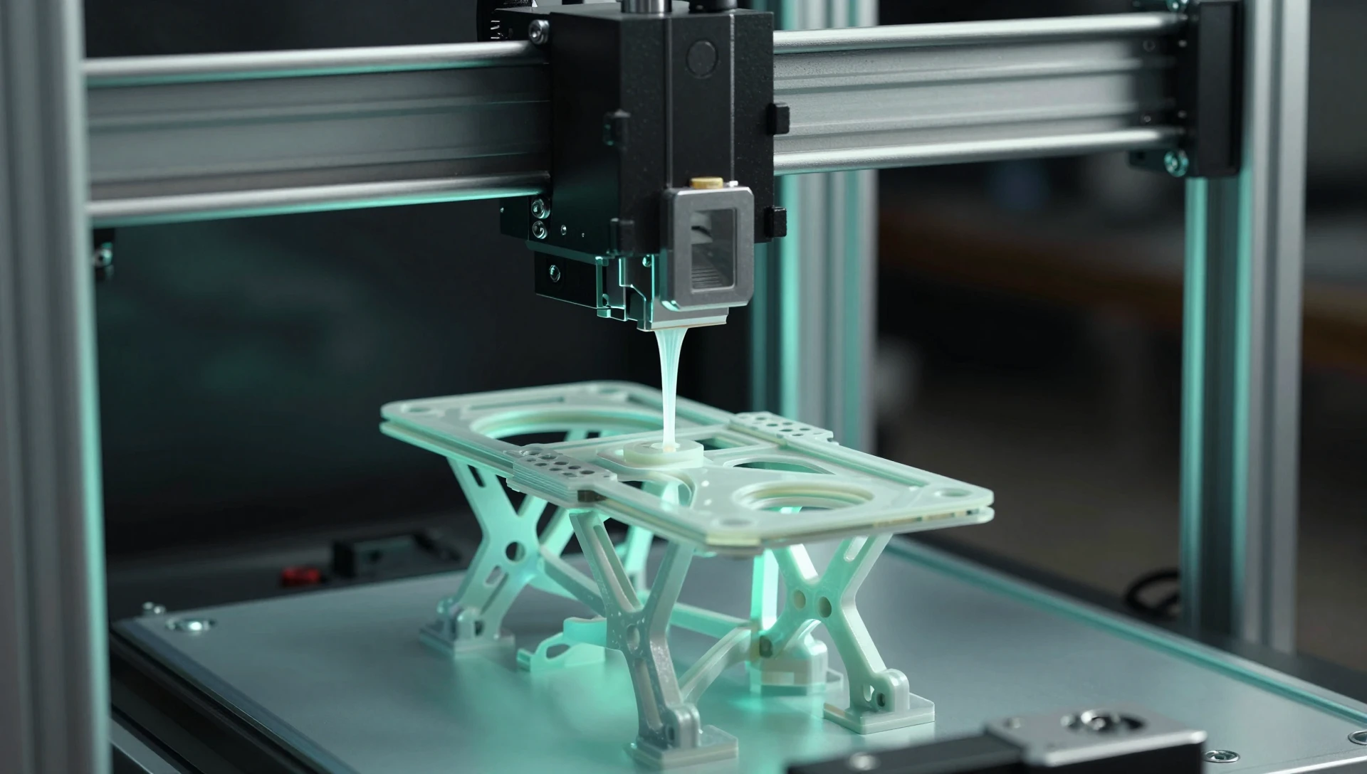
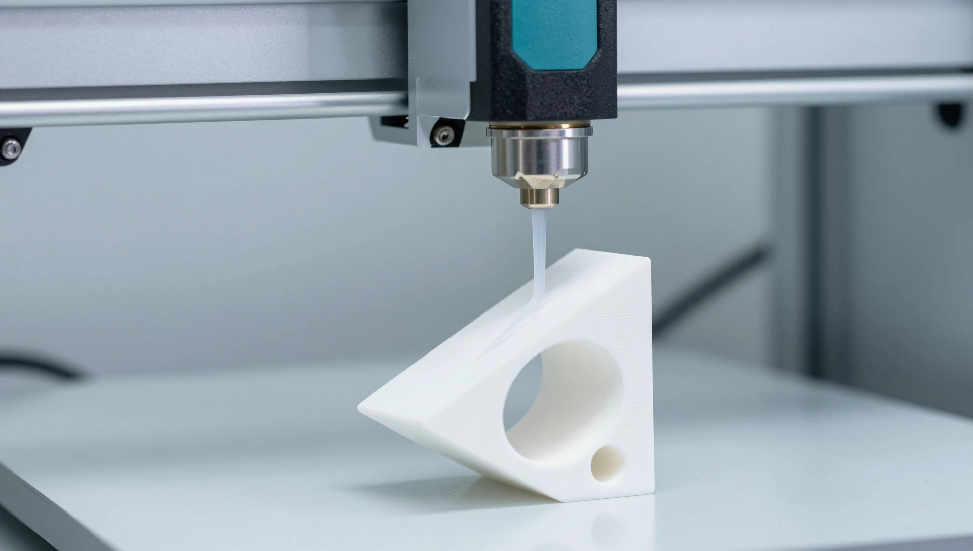
FDM printers deposit molten filament layer by layer. Every new layer needs a surface beneath it. When geometry angles away at more than roughly 45° from horizontal, unsupported filament droops, sags, or collapses mid-air. Support structures are the temporary scaffolding printed alongside or below the part to catch those areas.
The problem is that supports cost you twice: once during printing (extra time, extra filament) and again during post-processing (removal effort, surface damage). A housing that genuinely needs supports for an internal undercut can be managed — you plan for it. A part that needs supports only because it was designed without considering print orientation is an entirely avoidable cost.
FDM Overhang Angle Guide — Understanding the 45-Degree Rule
The 45° threshold is the standard starting point for FDM design decisions: angles shallower than 45° from vertical are generally self-supporting. Steeper than 45° and you need either supports or a design change.
Layer height shifts this threshold. At 0.10 mm layers with good part cooling, many printers handle 55°. At 0.30 mm layers, 40° is safer. PLA bridges cleanly in most conditions; PETG and ABS are more sensitive to cooling and tend to sag earlier. Design for 45° and treat any extra capability as a bonus, not a design requirement.
Horizontal bores are the most common problem. A 6 mm hole parallel to the build plate bridges without supports. A 30 mm hole at the same orientation will sag at the crown. The standard SolidWorks fix is a teardrop profile — flat side faces up, pointed end faces the build direction. That geometry change eliminates internal supports in the majority of horizontal bore cases and takes under two minutes to model.
3D Print Support Structures Guide — Linear, Tree, and Custom
This 3D print support structures guide covers what you will encounter in PrusaSlicer, Bambu Studio, or Cura:
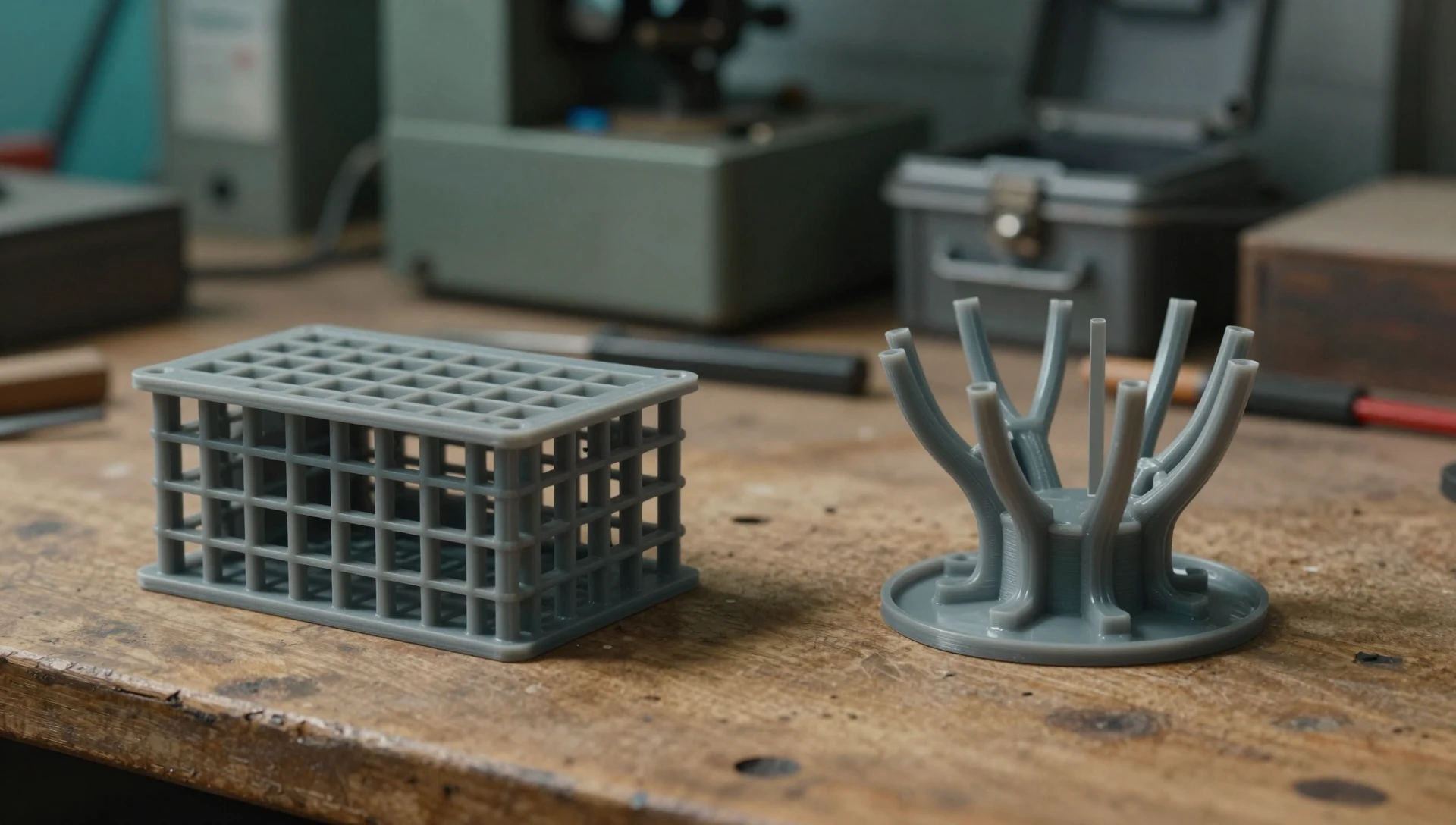
Linear supports (grid or rectilinear) are the slicer default. They grow straight from the build plate in a regular grid and handle large flat overhangs reliably. They are simple to configure but leave flat witness marks on supported faces and are difficult to remove from tight internal features.
Tree supports use branching structures that extend from the plate and curve to touch only necessary contact points. They typically use 20–35% less material than linear supports on equivalent geometry, leave smaller contact marks, and separate more cleanly from organic or curved surfaces. For parts with multiple isolated overhangs at different heights, tree supports are the stronger choice.
Custom (painted) supports let you specify exactly where support material lands. For engineering parts with tight tolerances on supported faces, this is the most controlled approach — more time in the slicer, but predictable surface quality where it matters most.
Designing Parts to Minimize 3D Printing Supports
Designing parts to minimize 3D printing supports is always better than optimizing how to remove them. The most effective strategies:
Orient before you finalize the model. Confirm the print orientation before adding final fillets and surface details, and check whether any face needs support at that orientation. Changing geometry at sketch level is fast; changing it after detailed modeling is not.
Chamfer downward-facing edges instead of using fillets. A 45° chamfer on a downward-facing edge is self-supporting. A convex fillet on the same edge almost always requires support. Both break sharp edges, but one is additive-manufacturing friendly.
Split complex parts at logical interfaces. A housing with deep internal channels can be split into two shells bonded together. Each half prints flat with no internal supports, and the bond line is often stronger than a support-contaminated interior surface. The extra part is nearly always worth the trade.
Add self-supporting transitions early. If a wall needs to transition from vertical to a shallow angle, set that angle to 45° in SolidWorks at sketch level. Changing a 35° draft to 45° takes seconds at that stage. Removing support material from a tight internal cavity after printing can take 20 minutes and still leave surface damage.
Support Settings That Change Results
When supports are unavoidable, three slicer settings matter most:
Interface layers — dense top-and-bottom layers between the support body and the model surface — significantly improve supported face quality and simplify removal. Enable them; two interface layers at 0.2 mm spacing is a reliable default in PrusaSlicer and Bambu Studio.
Z-distance (support gap) is the vertical clearance between the support top and the model. For PLA, 0.2 mm. For PETG, increase to 0.3 mm — PETG adheres aggressively to itself and needs more gap to release cleanly.
Support density at 10–15% is typically sufficient. Supports need to be stiff enough to resist the depositing nozzle, not structurally solid. Higher density wastes material and makes removal significantly harder.
Support Removal 3D Printing — Getting Clean Results
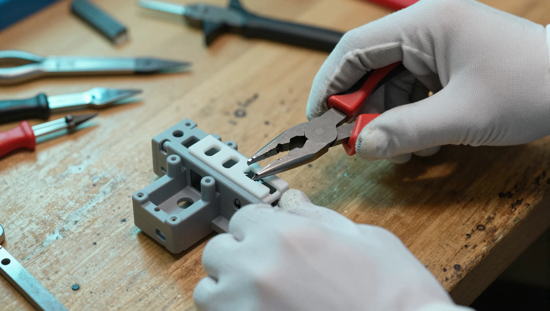
Support removal 3D printing is as mechanical as it is material-dependent. For external linear supports, needle-nose pliers and a flush cutter handle most cases. Twist rather than pull straight — supports break cleanest at their narrowest section, not by tearing from the model surface.
Internal supports inside channels and bores are the hardest to remove without damaging surrounding geometry. Soluble supports solve this entirely: PVA dissolves in water (compatible with PLA); HIPS dissolves in limonene (compatible with ABS). If your part has hidden internal features with overhangs and tolerances that matter, confirm dual-extrusion soluble support availability with your 3D printing service before the job runs.
After removal, supported surfaces typically need 220–400 grit sanding to remove witness marks. If a supported face is a mating surface with a dimensional tolerance, plan for 0.2–0.5 mm of material variation in that region and machine, ream, or tap to final size.
When the Answer Is Redesign, Not Better Removal
If post-processing on supported faces consistently takes more than 15 minutes per part, or if support removal repeatedly damages the geometry, redesign is cheaper than iterating on the same print. A targeted geometry review — adjusting overhangs, splitting bodies, adding self-supporting features — typically reduces support volume by 50–80% without changing part function. For runs of 10–100 units, those savings compound on every build. For a complete set of FDM geometry rules, see our 3D printing design rules guide.
Ready to turn your idea into a 3D CAD model? MiniCAD has delivered 7,000+ orders over 9+ years, rated 4.9 out of 5 across 4,470+ Fiverr reviews.
Packages start at $79. Send your sketch, photo or sample through our quote form and get a personal quote within 24 hours. You pay only after you accept it. Questions? Email contact@minicad.io.