If you have designed a part for 3D printing and plan to eventually manufacture it via injection molding, you are going to hit a wall — the design rules are completely different. Understanding how design for injection molding vs 3D printing diverges is the difference between a prototype that validates your concept and a production-ready file your toolmaker can actually use. This guide covers every critical geometric constraint before your SolidWorks model becomes a mold tool.
Why the Two Processes Demand Completely Different Designs
3D printing builds geometry layer by layer, bottom to top. You can print overhangs, internal channels, and complex lattices that would be physically impossible to eject from a steel mold. Injection molding fills a rigid tool cavity with molten polymer under high pressure, then opens the tool along a parting line to eject the part. Every geometric decision you make in SolidWorks must respect that opening-and-ejection sequence — or your part will lock inside the tool. That means scrap, mold rework, and thousands of dollars lost before the first production unit ships.
The practical consequence: a 3D-printed prototype file is almost never production-ready as-is. Treating it as one is the single most expensive mistake product developers make when scaling from samples to volume.
Wall Thickness: Where Injection Molding Design Guidelines Begin
For FDM 3D printing, wall thickness between 1.2 mm and 3 mm works reliably for structural parts. You can also vary wall thickness freely across a single part — the printer deposits material wherever the slice file dictates, with no downstream consequence from the variation itself.
Injection molding imposes much tighter control. The target range for most engineering-grade thermoplastics — ABS, PP, Nylon, and PC — is 1.5–4 mm, and the variation rule is strict: adjacent walls should not differ by more than 25–30% of the thicker section. A sudden transition from 1.5 mm to 4 mm creates a shrinkage differential as the thicker section cools more slowly. The result is a visible sink mark on the outer surface and internal stress that weakens the part in service. In SolidWorks, use Evaluate → DFMXpress to flag wall-thickness violations before you hand off any file to a toolmaker.
Draft Angle Injection Molding Requirements — Getting the Taper Right
Draft angle is the taper applied to vertical walls so the part releases cleanly when the mold opens. 3D printing requires zero draft — your walls can be perfectly vertical or even slightly undercut. Draft angle injection molding requirements are non-negotiable: a minimum of 1° per side on most smooth surfaces, and 3° or more on any textured, sandblasted, or spark-eroded wall. Without sufficient draft, the part grips the core steel as it shrinks during cooling. Ejector pins then either leave witness marks or, in the worst case, permanently distort the geometry.
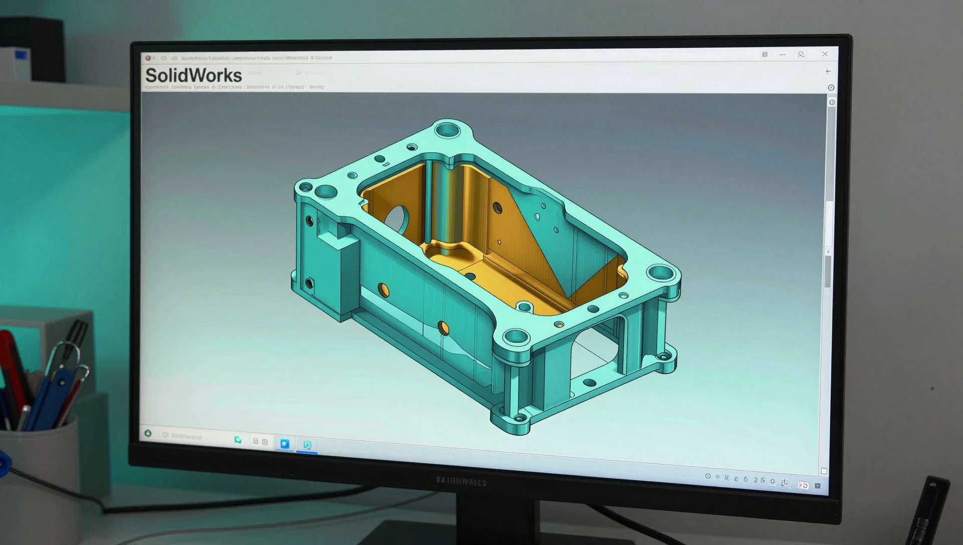
In SolidWorks, add draft as a dedicated feature after you finalize overall geometry. Use Insert → Features → Draft, define your parting line, and apply 1.5° to smooth surfaces and 3° to textured areas. If a boss, rib, or snap-fit feature prevents full draft without losing function, flag it for your toolmaker early — they may relocate the gate or add a lifter rather than reject the entire design.
Undercuts — The Feature That Can Stop a Mold Cold
An undercut is any geometry that prevents the mold halves from separating in a straight line. 3D printing handles undercuts effortlessly with support material. Injection molding cannot — unless the toolmaker adds a side action (a moving mold element that retracts before ejection) or a collapsible core. Both options add significant tooling cost: a basic side action typically adds $800–$3,000 to the quote and extends the tool build schedule by one to two weeks.
Common undercuts to eliminate during the redesign phase: side holes without through-wall clearance, external threads molded in rather than cut post-process, snap-fit hooks that face inward, and logo recesses placed directly on the parting line. Use SolidWorks Evaluate → Draft Analysis to highlight every surface that would block ejection — work through that list before sending any file to a toolmaker.
When to Switch from 3D Printing to Injection Molding
The volume crossover depends on part size and material, but a reliable rule of thumb for consumer-product parts under 200 cm³ is around 500–1,000 units. Below that threshold, the per-unit cost of 3D printing — typically $3–$20 per part in PLA, PETG, or ABS — is competitive with the amortized tooling cost. Above it, injection molding unit cost ($0.10–$2.00 for most small parts) rapidly wins even after paying $4,000–$15,000 for the tool.
The other trigger is material. If your product needs glass-filled nylon for stiffness, polycarbonate for optical clarity, or FDA-compliant PP for food contact, injection molding opens a material library that FDM and SLA printing cannot match at production quality or cost. The goal of the 3D printing phase is not to build the final part — it is to validate geometry cheaply so you de-risk the tooling investment.
Injection Molding Design Guidelines — A Practical Pre-Production Checklist
Before converting a printed prototype file to a production-intent SolidWorks model, verify every item on this list:
Uniform wall thickness within ±25% of the nominal section. Minimum 1° draft on all vertical walls; 3° on textured surfaces. No undercuts without a corresponding side-action or lifter callout. A clear parting line that follows the part’s natural silhouette. Gate location placed away from visible cosmetic surfaces. Rib height below 3× the rib thickness to prevent sink marks. Inside corner fillets ≥ 50% of the wall thickness to reduce stress concentration. Ejector pin locations defined on non-cosmetic surfaces.
Engineers who review 3D printing design rules in parallel with this injection molding checklist during the prototype phase typically eliminate 80% of the redesign cycles that otherwise appear at first-article review — when time and tooling budget are already committed.
Design for Injection Molding vs 3D Printing — The Cost Crossover
A concrete example: a palm-size ABS housing printed on an FDM machine costs roughly $8 per unit at low volume. The same part injection molded in ABS costs $0.40 per unit at 10,000 units — but the tool costs $6,000. Break-even: 6,000 ÷ ($8 – $0.40) ≈ 790 units. If you plan to sell more than 800 units, injection molding wins on unit economics alone, before factoring in surface quality and material consistency.
For SLA and engineering resins, the crossover is earlier — photopolymer resins cost $30–$150 per kilogram, which makes even modest production runs favor tooled processes quickly. 3D printing vs injection molding for production is ultimately as much a business decision as an engineering one — the geometry follows the economics, not the other way around.
Preparing the Production-Intent SolidWorks File
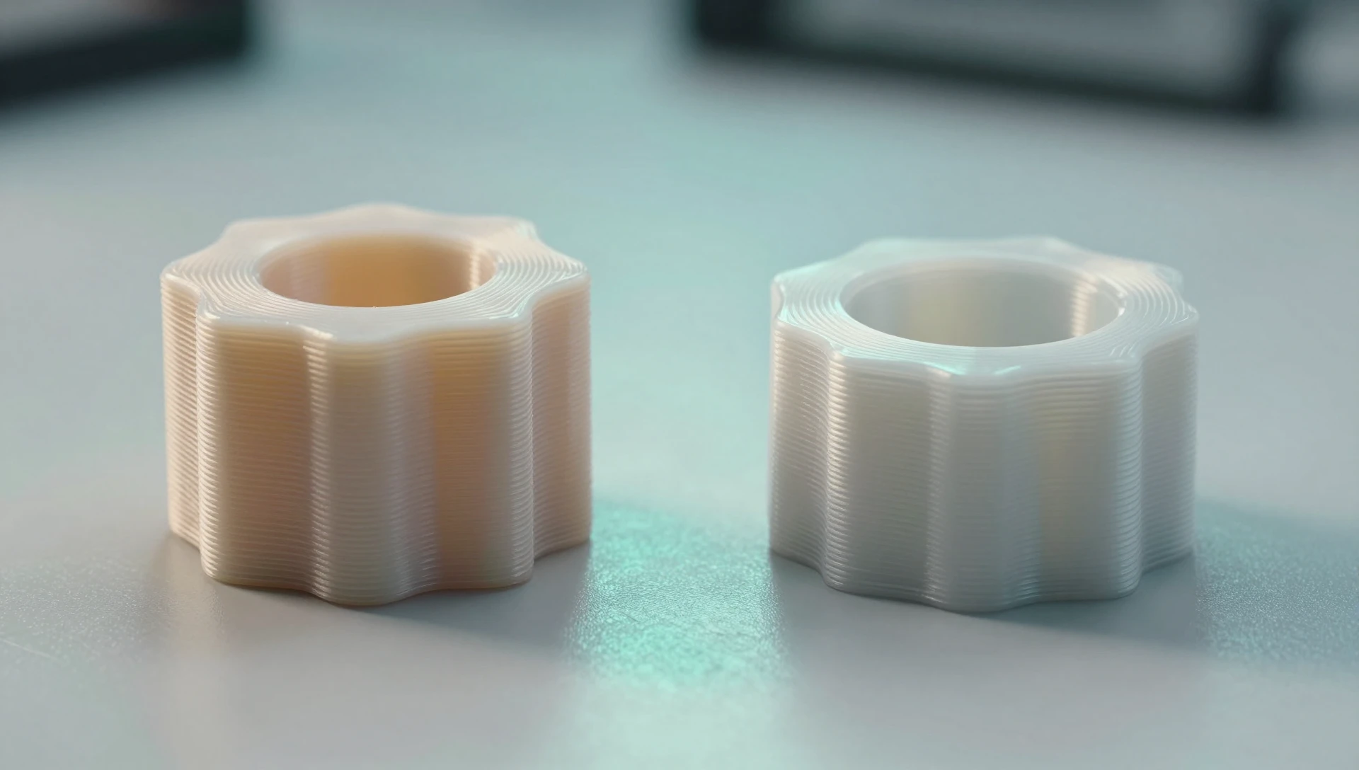
The most efficient product development workflow is to prototype in 3D printing with no manufacturing constraints — validate fit, prove the concept, test assembly. Then redesign the SolidWorks file with all injection molding constraints applied before going to tooling. These are two different files with two fundamentally different sets of design intent. Trying to use your printing file as your production file is one of the most common — and costly — errors at the prototype-to-production transition. According to Xometry’s DFM resources, design-for-manufacturing errors are among the leading causes of first-article failures and tooling rework.
At MiniCAD, our team has delivered 7,000+ CAD projects across 40+ countries, producing SolidWorks STEP and SLDPRT files built to pass DFM review the first time. We handle the complete transition from 3D-print prototype to injection-mold production geometry — 24-hour delivery, 4.9★ rating across 4,470+ verified reviews. Ready to prepare your production file? Send your brief at minicad.io/quote/ or reach us at contact@minicad.io.