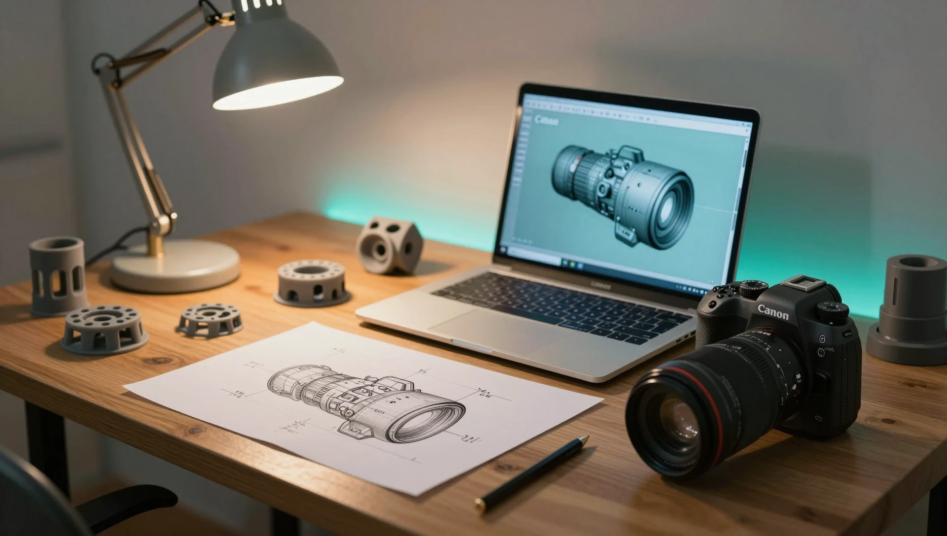
Every inventor hits the same wall. You have sketched your idea dozens of times, you know exactly how it should work — and now the next step is product design for inventors, but nobody explains what that actually means in practical terms. It means translating your sketch into a precise, manufacturable 3D CAD model that factories, 3D printers, and patent offices can work from. Getting this step right saves thousands of dollars and months of rework. Getting it wrong costs both.
What Makes Product Design for Inventors Different
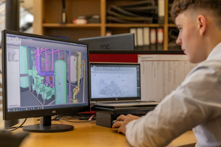
When a company commissions a CAD model, the engineer already knows the manufacturing process, the material, and the required tolerances. Most inventors do not — and that is not a problem, it is just a different starting point. The challenge is that an inventor’s design often needs to serve three purposes simultaneously: prove the concept works, support a patent application, and be manufacturable in a real material at a real cost. Each purpose puts different demands on the CAD model. A patent drawing emphasizes geometry and the uniqueness of claimed features. A 3D-printed prototype emphasizes wall thickness and clearances. A production mold demands draft angles and consistent wall depth. The CAD file that satisfies all three is the goal — and building it that way from the start is far cheaper than retrofitting it later.
Define Your Scope Before Anyone Opens SolidWorks
Before a single feature gets sketched in SolidWorks, write down what your model needs to accomplish at the end of this project. Does it need to be 3D-printable today? Do you need STEP files for a manufacturer quote? Is a patent drawing the immediate deliverable, or a render for a crowdfunding page? Each answer changes what the designer builds and how they build it. Skip this step and you will often pay for a fully detailed, surface-finished model when a simpler parametric solid would have served your immediate need — or receive a quick mesh that a machinist cannot quote from. Define the deliverable before the work begins, in writing, before you share your first sketch.
Choosing the Right Output Files for Your Stage
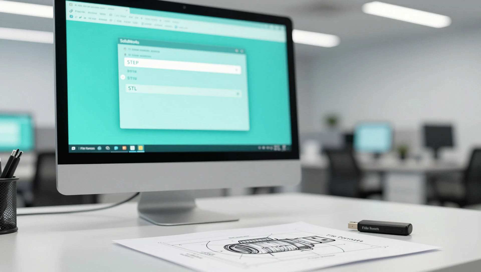
Inventors typically need one or more of the following file types, and knowing which to request saves revision cycles and cost:
STEP (.step / .stp) — the universal exchange format for manufactured parts. Every contract manufacturer, injection molder, and CNC shop can read it. Request STEP for any production-intent quote or machining work.
STL / 3MF — mesh formats for 3D printing. Excellent for rapid prototypes and fit-check models. Not suitable for manufacturing quotes because they carry no editable dimensional parameters.
SLDPRT (SolidWorks native) — the fully parametric source file. If your design will evolve — and it always does — the native file lets any SolidWorks engineer modify features directly instead of rebuilding from a static mesh. Always request this alongside the export formats.
Technical drawing (PDF or DWG) — annotated 2D views with tolerances, surface finishes, and manufacturing notes. Required by most contract manufacturers before they will quote, and essential for patent applications. Without it, a factory must interpret the 3D model and guess at critical dimensions.
How to Design a Product for Manufacturing From the First Model
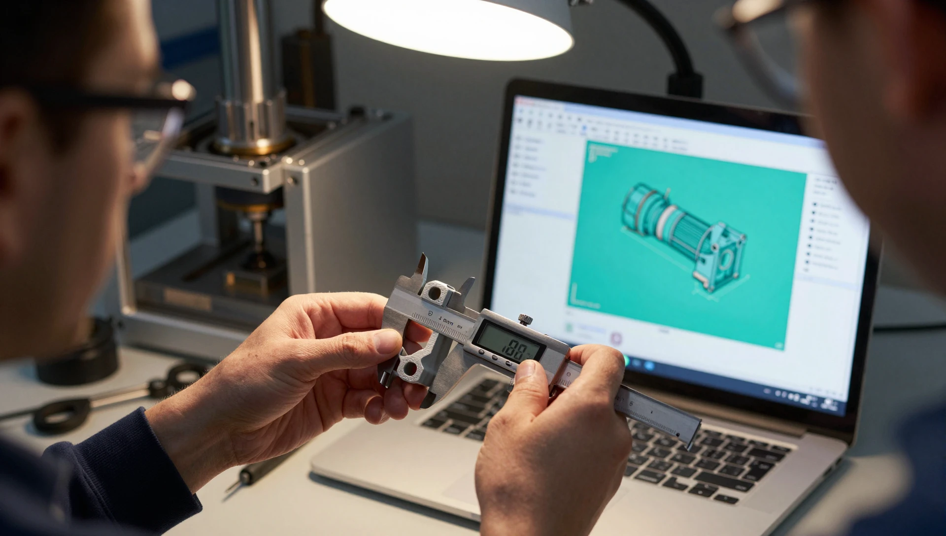
One of the most expensive mistakes in inventor product development is designing a part without understanding how it will be made. A shape that looks correct in a render will often fail in manufacturing — draft angles are missing, walls are too thin for the mold, or tolerances are tighter than the process can hold. Knowing how to design a product for manufacturing means baking these constraints into the first model, not correcting them after a factory rejects your file.
For 3D-printed prototypes, the key rules are: minimum wall thickness of 1.2 mm for FDM and 0.8 mm for SLA; overhangs supported below 45 degrees; no unsupported features smaller than your nozzle diameter. For injection molding — where most inventors land for production quantities — every vertical wall needs 1–3 degrees of draft angle, and wall depth should stay between 1.5 mm and 4 mm for most engineering thermoplastics. According to Protolabs’ manufacturing design resources, more than 60% of first-time injection mold submissions require significant revisions before tooling can begin. Fixing those issues at the CAD stage costs a few hundred dollars. Fixing them after a steel mold is cut can cost tens of thousands.
How CAD Models Support Your Patent Application
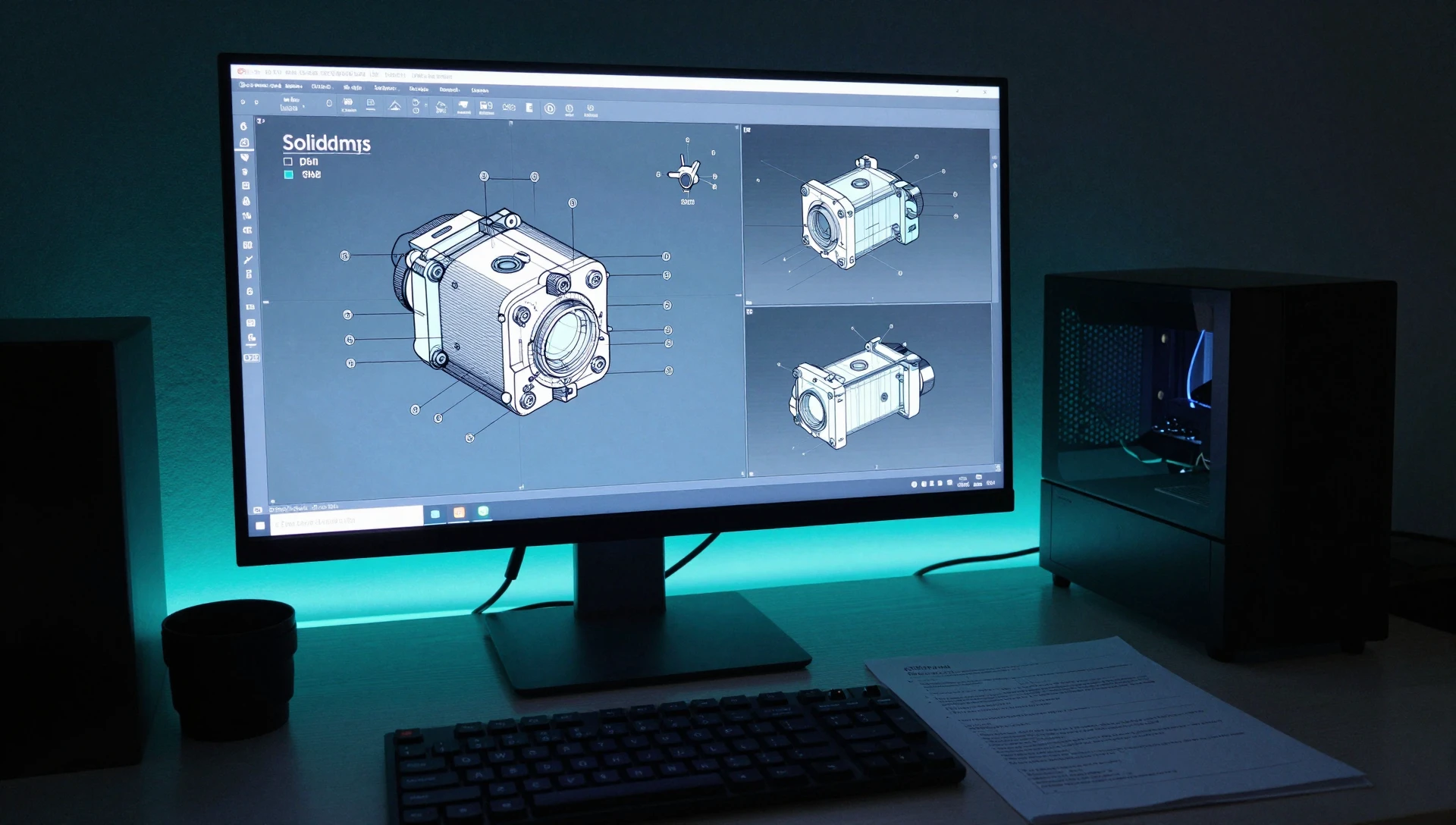
A well-built CAD model does more than enable prototyping — it feeds directly into your IP strategy. A CAD model for patent filing is not the same as a production model. Patent offices require formal patent drawings — black-and-white line-art views showing all claimed features from multiple projection angles, with numbered leaders, cross-section hatching, and no dimension callouts. These are derived from the 3D model but need specific formatting that differs from a standard engineering drawing. SolidWorks handles this well: a drawing template can be configured to match patent-office requirements, and the views update automatically when the model changes. Have your CAD designer produce both the parametric 3D solid and the patent-style 2D drawing sheets in one deliverable. When the design evolves — and it will — updating both files is a single operation instead of a full rebuild.
When to Handle It Yourself vs. Bring In a Professional
Effective product design for inventors does not require you to learn CAD software — but it does require that you understand what you are purchasing. Basic geometric shapes, simple housings, and single-material brackets can be modeled in beginner-level tools. Anything with multiple mating parts, specific dimensional tolerances, complex curvature, or direct manufacturing intent needs SolidWorks and the engineering judgment that comes with years of DFM experience. The practical test: if a manufacturer rejecting your submitted file would cost you more — in time, tooling deposits, and delayed launch — than the CAD work itself, hire a professional. Our studio handles inventor projects starting at $34 for simple components, with most first-prototype scopes landing in the $69–$174 range depending on complexity and deliverable count.
How to Bring a Product Idea to Market After the CAD Stage
The CAD model is not the finish line — it is the handoff document for every step that follows. Here is how to bring a product idea to market from the CAD stage: use the STEP file to collect manufacturer quotes and compare materials and processes; 3D print a functional prototype from the STL to validate fit, feel, and function before committing to tooling; deliver the technical drawing to your patent attorney as the backbone of your utility application; use a photorealistic render — which a SolidWorks model supports directly through PhotoView — for crowdfunding pages, Amazon listings, and investor decks before physical stock exists. Each step flows from a single well-built parametric model. Skimping on the CAD foundation forces you to rebuild assets at every stage instead of deriving them from one source of truth.
Ready to move your invention from sketch to a manufacturable, patent-ready 3D model? Our studio has handled prototype and inventor design projects across 40+ countries — 7,000+ completed orders, 4.9★ rating from 4,470+ verified reviews, and 24-hour delivery on most scopes. Submit your concept at minicad.io/quote to get a same-day estimate. Questions? Email contact@minicad.io.