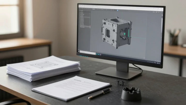
Your machinist asks for the model, you open the Save As dropdown, and there are nine formats staring back at you. The IGES vs STEP file question looks like a clerical detail, but it decides whether the shop opens a watertight solid and starts programming in twenty minutes, or opens a bag of disconnected surfaces and spends an afternoon stitching them back together before anyone touches a toolpath. We deliver files to machine shops, injection molders, and print farms in more than 40 countries every week, and format choice is still the single most common reason a handoff stalls.
IGES vs STEP File — What You Are Actually Choosing
Both formats are neutral: they let a model move between CAD systems that do not read each other’s native files. That is where the similarity ends. IGES (Initial Graphics Exchange Specification) was published by the US National Bureau of Standards in 1980 and effectively froze at version 5.3 in 1996. It describes a part as a collection of curves and trimmed surfaces. Nothing in the format guarantees those surfaces meet, so the receiving system has to knit them into a solid and hope the gaps are small enough.
STEP (ISO 10303) is the modern replacement and it is still actively maintained. It carries B-rep solid bodies — faces plus the topology that says which face touches which edge — so a valid STEP file arrives as a closed solid, not a puzzle. In practice that is the whole argument. If the receiving system reads STEP, send STEP.
How IGES and STEP Store Geometry Differently
Picture a simple bracket with a filleted corner and two counterbored holes. In STEP, the file records the solid: 14 faces, the edges between them, and the fact that the body encloses volume. Import it, and SolidWorks reports one solid body. Mass properties work. You can shell it, add a boss, or run a draft analysis immediately.
In IGES, the same bracket is stored as 14 independent trimmed surfaces plus their boundary curves. On import, SolidWorks tries to knit surfaces whose edges fall within roughly 0.0025 mm of each other. Curved faces translated through a different math tolerance frequently miss that window. The result is a surface body with two or three missing patches — usually at fillet tangency or at a hole break — and someone has to rebuild them by hand.

Neutral CAD File Formats Compared
Four neutral CAD file formats cover almost everything you will be asked for:
- STEP (.step, .stp) — solid B-rep, ISO-maintained, read by every current CAD and CAM system. AP203 carries pure geometry. AP214 adds colors and layers. AP242 merges both and can carry PMI, so tolerances and datums travel with the model.
- IGES (.igs, .iges) — surfaces and curves, frozen since 1996. Still required by some legacy CAM seats, wire EDM controllers, and older surfacing packages.
- Parasolid (.x_t, .x_b) — the native kernel format behind SolidWorks, NX, Onshape, and Solid Edge.
- ACIS (.sat) — the equivalent kernel format for AutoCAD, Inventor, and a handful of analysis tools.
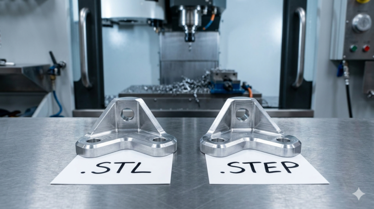
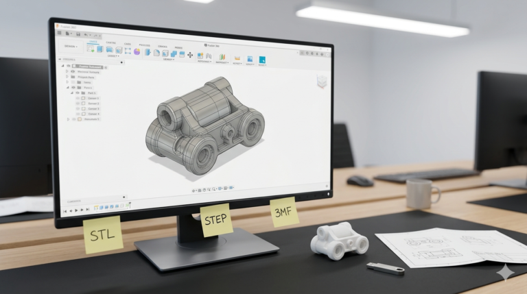
Meshes are a separate category. STL and 3MF describe a triangulated skin with no underlying math, which is correct for a printer and wrong for a machine shop. That trade-off is covered in our breakdown of which file to send your manufacturer.
Parasolid vs STEP File — When the Kernel Format Wins
SolidWorks is built on the Parasolid kernel, so exporting to .x_t skips translation entirely — the geometry is written in the language the kernel already speaks. In a Parasolid vs STEP file comparison, Parasolid wins on two measurable counts. Accuracy: no tolerance conversion, so no seam errors. Size: the binary .x_b of a 60-part assembly we delivered last quarter came to 9 MB against 34 MB for the same assembly as ASCII STEP.
The catch is reach. Parasolid only helps if the recipient runs a Parasolid-based system. Ask first. If they say Inventor, SolidWorks Composer, CATIA, or “our CAM guy handles it,” send STEP AP214 and stop guessing.
Native CAD File Versus Neutral Format
Every neutral format is a dumb solid. STEP, IGES, and Parasolid all discard the feature tree — the sketches, the dimensions, the parametric relationships, the design intent. Open a translated part and you get one imported feature with no history. Changing a wall from 3 mm to 4 mm is no longer a dimension edit; it is a Move Face operation, or a rebuild.
Native SolidWorks files (.SLDPRT, .SLDASM) keep all of it. That is why any studio worth hiring hands over the native files alongside the neutral ones. A native cad file vs neutral format decision is really a question of who owns the design six months from now. If you only hold a STEP file, your next revision costs modeling hours that a .SLDPRT would have made free. Our SolidWorks modeling work ships a print-ready mesh plus STEP with every package, and the native files from the Complex Part package up, so clients are never locked out of their own geometry.
How to Export a STEP File From SolidWorks Correctly
The default settings are fine most of the time, but three of them matter:
- Pick the protocol deliberately. File > Save As > STEP > Options. AP214 for anything going to a shop that wants face colors. AP242 when the recipient confirms they can read PMI. AP203 when in doubt — it is the most universally supported.
- Export assemblies as a single file. Leave “Export assembly as multiple bodies” unchecked so the part structure survives instead of collapsing into one lump.
- Run Tools > Check before you export. Invalid faces and self-intersecting geometry translate into an unusable STEP file, and the error surfaces on the recipient’s screen rather than yours.
Then reopen your own export in a fresh SolidWorks window. Thirty seconds of verification catches the failure before your supplier does. The SolidWorks help documentation lists the full option set for each protocol.
What to Do When a Translated Model Arrives Broken
When an imported file lands as a surface body, resist the urge to remodel from scratch. Run Import Diagnostics first — it appears automatically on import failure, or right-click the imported feature and choose it. It reports faulty faces and gaps, and its automatic repair fixes most translation damage in a single pass. If three or four patches remain, rebuild only those with Filled Surface, then knit and thicken.
Remodeling wins in one situation: when the part needs real design changes, not just repair. A dumb solid that has to grow a new mounting boss and change wall thickness is faster to rebuild parametrically than to push and pull with surface tools — and you finish with a live feature tree instead of frozen geometry.
The IGES vs STEP file decision resolves into one habit worth keeping: send STEP by default, Parasolid when the recipient runs the same kernel, IGES only when someone specifically asks for it, and always keep the native file for yourself. That habit removes most of the friction in a manufacturing handoff.
Ready to turn your idea into a 3D CAD model? MiniCAD has delivered 7,000+ orders over 9+ years, rated 4.9 out of 5 across 4,470+ Fiverr reviews.
Packages start at $79. Send your sketch, photo or sample through our quote form and get a personal quote within 24 hours. You pay only after you accept it. Questions? Email contact@minicad.io.