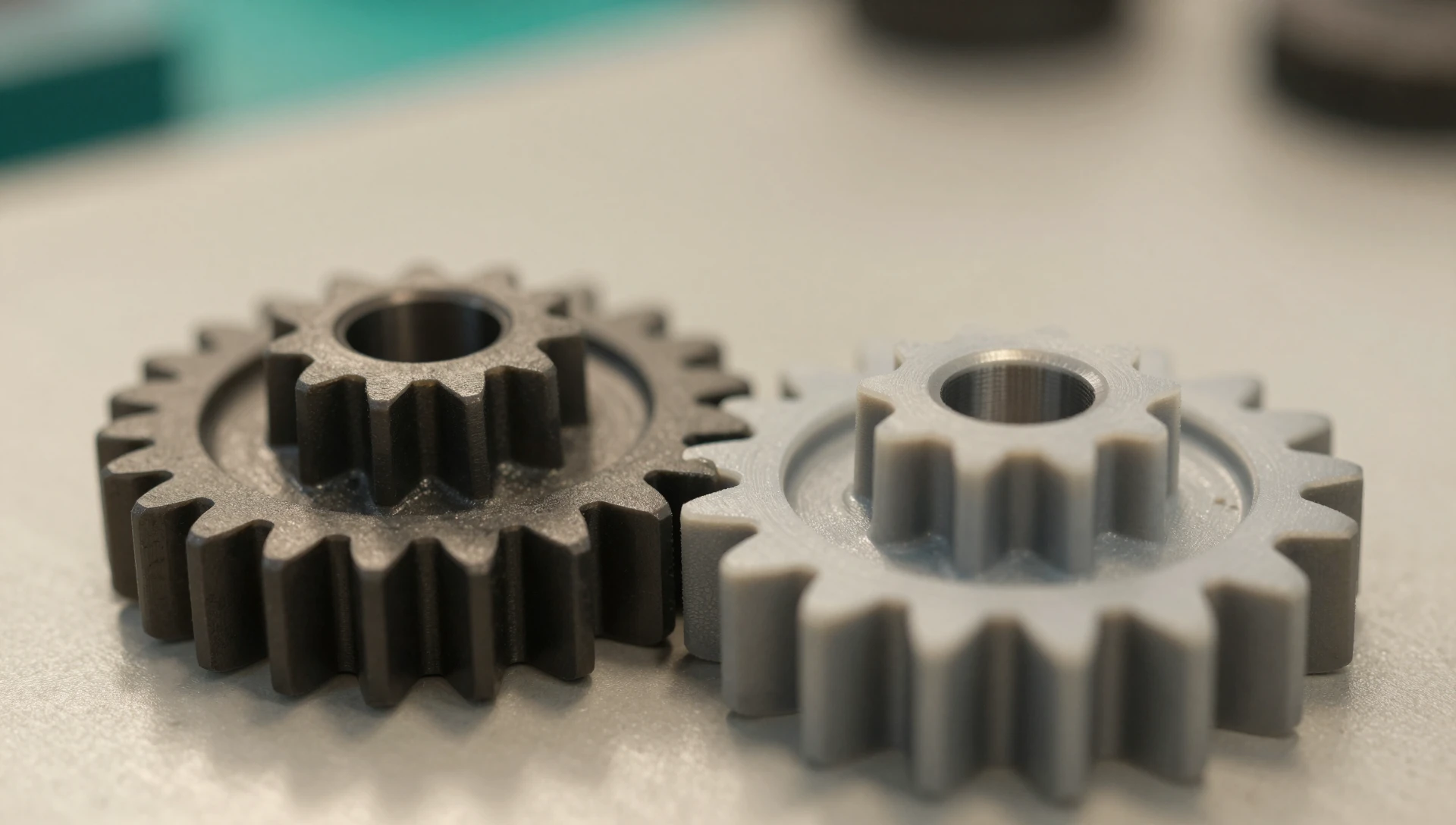
Your printed gear meshes for ten minutes, then the teeth round over and the drive slips. Almost every failure like that traces back to 3D printed gear design decisions made in CAD — module, tooth count, backlash, print orientation — not to the printer. A gear drawn with textbook geometry and sent straight to a slicer will bind or skip: an FDM machine builds teeth in 0.4 mm beads and every surface lands 0.1–0.2 mm oversized. Here is the approach we use on production parts.
Why 3D Printed Gear Design Is Different From Machined Gears
A hobbed steel gear is cut to profile within 0.02 mm and runs on hardened teeth. A printed gear is grown from extruded plastic, so three things change at once. Teeth come out thicker than modeled because of extrusion width. The material is roughly a thousand times less stiff than steel, so teeth deflect under load instead of holding profile. And the part is anisotropic — measurably weaker across layer boundaries than along them. So you cannot scale down an industrial drawing: you need a coarser tooth, a wider face, a deliberate flank gap, and an orientation that keeps tooth load inside a layer.
Gear Module for 3D Printing, Pressure Angle, and Tooth Count
Module is tooth size — pitch diameter divided by tooth count — and it is the most important number in the design. For FDM, module 1.0 is the practical floor and 1.5 to 2.0 is the sweet spot. At module 1.0 with a 0.4 mm nozzle a tooth is only about three extrusion widths thick at the root: no solid core, just perimeters touching. Resin printers hold module 0.5 cleanly because they are not bound by nozzle width.
Pressure angle sets tooth shape. The 20 degree standard is the right default and matches almost every off-the-shelf gear. If the pair is fully custom and torque is the concern, 25 degrees gives a thicker tooth root and better bending strength, at the cost of higher radial load on the bearings.
Tooth count has a hard limit. Below 17 teeth at 20 degrees, standard involute profiles undercut — material is removed from the tooth base, exactly where it breaks. Stay at 17 or above on the pinion, or apply a positive profile shift of about +0.3 module. Ratio is simply the tooth-count ratio, and center distance follows: a 20-tooth pinion and 40-tooth gear at module 1.5 gives (20 + 40) × 1.5 ÷ 2 = 45 mm.
Spur Gear Design for 3D Printing — The Numbers That Matter
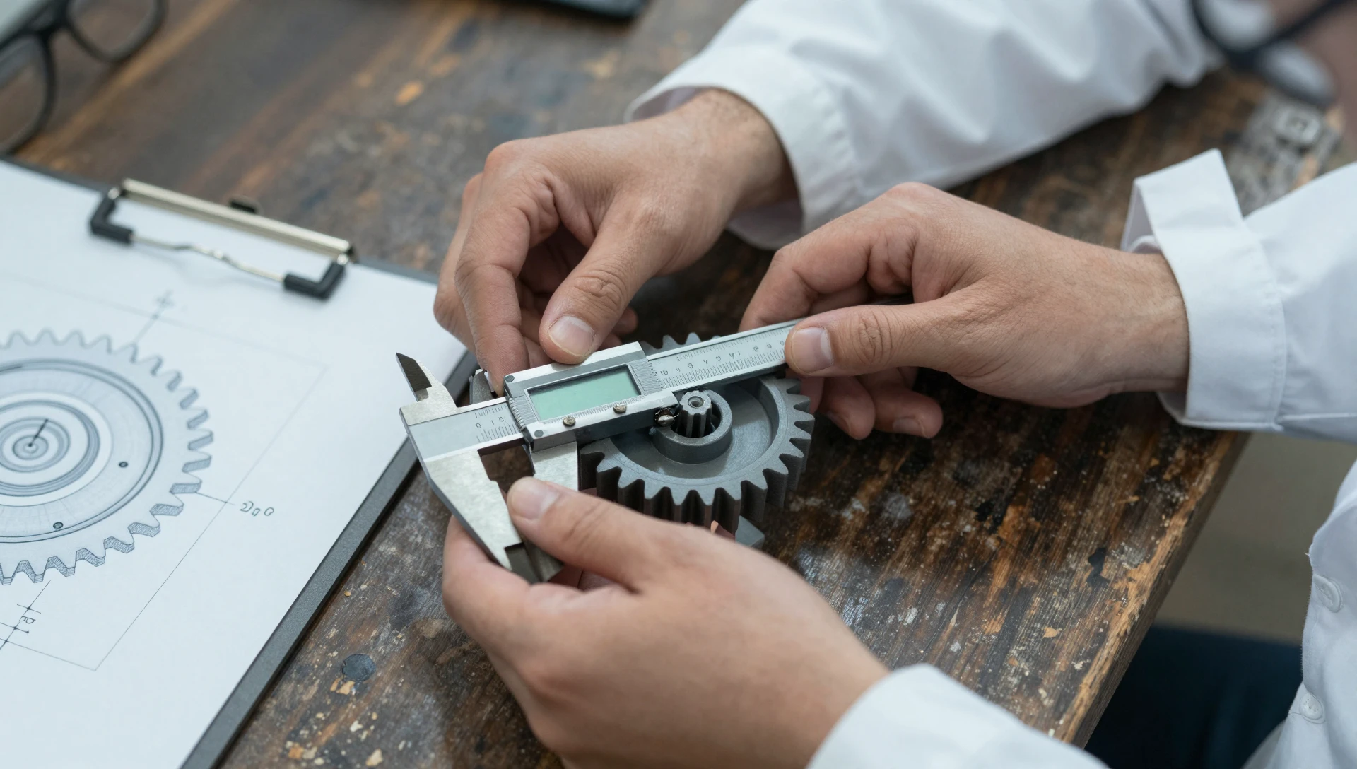
Spur gears are the correct choice for printed drives. Helical gears run quieter, but the helix angle forces teeth to build as stepped layers, which wrecks the contact line and adds axial thrust your printed hub was never designed to take. Use these figures as a starting point: face width 6 to 10 times the module, so a module 1.5 gear gets a 9 to 15 mm face. Addendum 1.0 module, dedendum 1.25 module, giving 0.25 module of tip clearance. Root fillet of at least 0.3 module — a sharp corner at the tooth base is a stress riser and a crack initiator in plastic. Rim thickness under the teeth of at least 3 module, so the tooth has something rigid to react against.
Backlash in 3D Printed Gears — How Much to Add
Backlash is deliberate clearance between mating tooth flanks, and this is where most designs fail. A printed pair modeled with zero backlash binds solid, because both gears print oversized and the errors add.
On a well-tuned FDM printer, add 0.15 mm to 0.30 mm of total backlash. The better method is to thin the tooth: reduce circular tooth thickness by 0.1 mm per flank on each gear, which keeps center distance nominal and preserves your bearing layout. The alternative — opening center distance by 0.1 to 0.2 mm — is faster but shifts contact up the tooth and cuts contact ratio. Start at 0.20 mm total, print a two-gear test pair, and spin it by hand. You want a faint rock at the tooth, not a click. If your printer is uncalibrated, measure a 20 mm test cube and fold the deviation in rather than guessing.
Best Material for 3D Printed Gears
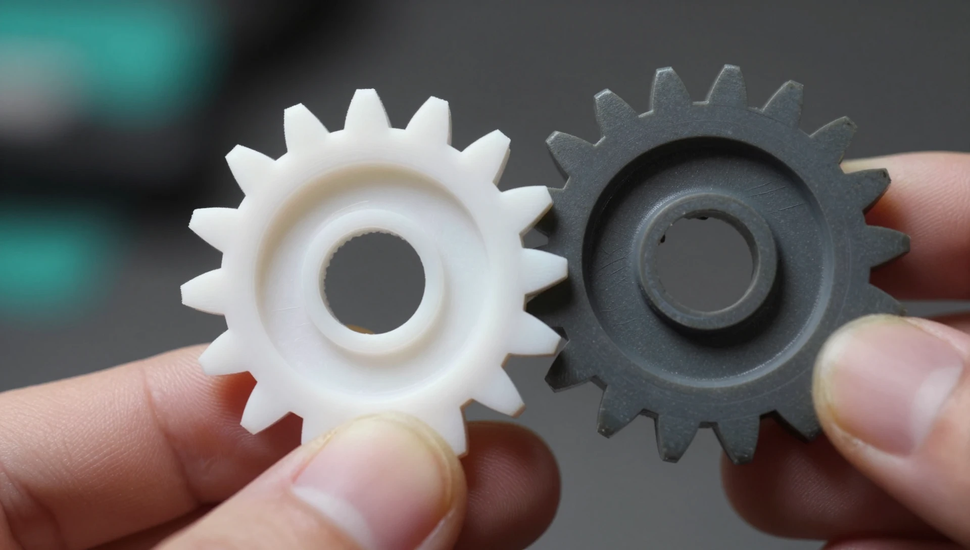
Material decides whether the gear lasts a weekend or a year. PLA is stiff and prints accurately, so it is fine for fit checks and low-load prototypes, but it creeps under sustained load and softens near 60 °C — a gear inside a warm enclosure slowly deforms. PETG is tougher but less stiff, with poor abrasion resistance, so teeth polish and round over. ABS sits in the middle and warps on large gears.
For anything that runs continuously, nylon is the answer. PA12 and PA6 are self-lubricating, tough, and survive repeated tooth impact without cracking. Carbon-filled PA6-CF adds the stiffness nylon lacks and holds dimension far better, at the cost of an abrasive filament that needs a hardened nozzle. Prototype in PLA, ship in PA12 or PA6-CF.
Print Orientation, Layer Height, and Tooth Strength
Print the gear flat on the bed with its axis vertical. This puts layers perpendicular to the axis, so tangential force on a tooth acts within a layer rather than pulling layers apart. Printing a gear on its side may look like it gives smoother flanks, but it loads every tooth across the weakest bond in the part, and teeth shear off cleanly at the layer line.
Drop layer height to 0.12–0.16 mm so the involute curve resolves properly instead of stepping. Set 4 to 6 perimeters so the tooth is solid wall material through its whole thickness, then 40 to 60 percent infill in the web. Perimeter count matters far more than infill on a gear, because the tooth is entirely a perimeter feature. Disable elephant-foot compensation, and print both gears in the same job.
Bores, Hubs, and Mounting the Gear to a Shaft
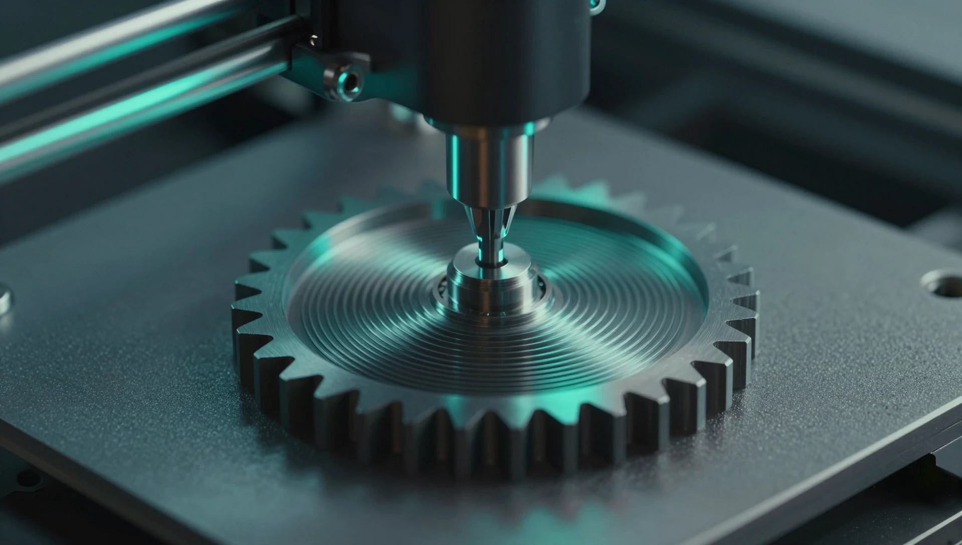
A perfect gear on a slipping hub is a failed part. Size the bore at nominal shaft diameter plus 0.2 to 0.3 mm on FDM, and model a D-flat that matches the shaft rather than relying on friction — for a 5 mm motor shaft, a 5.2 mm bore with a 4.5 mm flat. Never thread a set screw directly into printed plastic on a driven gear; the threads strip within a few hundred cycles. Design an M3 heat-set insert boss with a 4.0 mm pilot hole and 2.5 mm of wall around it. Extend the hub 8 to 12 mm along the shaft so the gear cannot cock over. Our guide to tolerances and clearances for printed parts covers the wider fit table.
A Practical 3D Printed Gear Design Checklist
Before committing filament: module 1.0 or above for FDM; pinion at 17 teeth or more, or profile shifted; total backlash 0.15 to 0.30 mm; face width 6 to 10 module; root fillets modeled; bore oversized 0.2 to 0.3 mm with a flat; heat-set insert boss instead of a threaded hole; gear flat on the bed at 0.12–0.16 mm layers with 4 to 6 perimeters; test pair printed and hand-spun before the full assembly. SolidWorks handles the geometry natively — its Toolbox gear generator produces a true involute profile you can then modify for backlash, which beats approximating tooth curves by hand.
Ready to turn your idea into a 3D CAD model? MiniCAD has delivered 7,000+ orders over 9+ years, rated 4.9 out of 5 across 4,470+ Fiverr reviews.
Packages start at $79. Send your sketch, photo or sample through our quote form and get a personal quote within 24 hours. You pay only after you accept it. Questions? Email contact@minicad.io.