
Your enclosure closes with a satisfying click, the screws pull it tight, and the first time it sits in rain the electronics inside are wet. A waterproof 3D printed enclosure fails for reasons that have nothing to do with print quality — it fails because the sealing surface, the groove, the fastener spacing and the wall structure were never designed to work together. This guide covers what actually keeps water out of a printed housing, with the dimensions we use on client parts every week.
Why a Waterproof 3D Printed Enclosure Leaks
There are only four leak paths in a two-part housing: the seam between lid and body, the fastener holes, the cable or connector openings, and the wall material itself. Most designers only think about the first one. FDM walls are the quiet failure — an extruded part is a stack of welded beads, and unless the perimeters overlap properly, water wicks straight through a 2 mm wall at zero pressure. We have pressure-tested parts at 100% infill that still bubbled under water because the shell had only two perimeters.
Fix the wall first, then the seam. Everything downstream depends on having a solid, non-porous shell to seal against.
What IP65 Enclosure Design Actually Requires
IP ratings are two digits: solids, then liquids. IP65 means dust-tight plus resistance to a 6.3 mm water jet at roughly 12.5 liters per minute from 3 meters. IP67 adds 30 minutes of immersion at 1 meter. A jet test is survivable with a compressed foam gasket; immersion demands a captured elastomer seal and a vent.
Decide the target before you model anything. IP65 enclosure design lets you use a 2 mm closed-cell foam strip and eight screws. IP67 means an O-ring in a real groove, a pressure-equalization vent, and sealed cable glands. Choosing IP67 late is a redesign, not a tweak.
O-Ring Groove Design for 3D Printed Parts
For a static face seal, the numbers are simple and they do not change because the part is printed. Take the O-ring cord diameter, call it d. Groove width is 1.3 to 1.4 × d. Groove depth is 0.70 to 0.75 × d, which puts the ring under 25–30% compression when the lid closes metal-to-plastic. For a common 2 mm cord: a groove 2.7 mm wide and 1.45 mm deep.
Two adjustments matter for printing. First, add 0.10–0.15 mm to the groove width to absorb extrusion width error — a printed groove almost always comes out narrower than modeled. Second, put the groove on the lid, facing up, so it prints as a simple recess with no supports and no bridging. Buying standard cord stock rather than molded rings keeps prototypes cheap; McMaster stocks metric cord you can cut and superglue into a loop for testing. Correct o-ring groove design for 3D printed parts is the single highest-return detail in the whole housing.
Gasket Design for a 3D Printed Enclosure Without Grooves
Not every project justifies a groove. When the seam is irregular or the wall is too thin to hold one, three alternatives work:
Closed-cell silicone foam tape, 1.5–3 mm thick, compressed to 50–70% of free height, is the fastest route to IP65 and tolerates a slightly warped lid. A die-cut 1.5 mm silicone sheet gasket on a flat 3 mm landing gives a cleaner seal and survives more open-close cycles. RTV silicone applied as a formed-in-place bead into a 1 mm × 1 mm channel seals best of all, but it makes the enclosure semi-permanent. Whichever you pick, gasket design for a 3D printed enclosure needs a flat landing at least 2.5 mm wide on both halves — a knife edge will cut the gasket, not seal it.
Sealing FDM Printed Parts Against Porosity
Sealing FDM printed parts starts in the slicer, not in post-processing. Use a 0.4 mm nozzle at 0.15–0.20 mm layer height, five perimeters minimum on a 2.4 mm wall, and raise extrusion multiplier by 2–3% so beads fuse rather than touch. Print in PETG, ASA or PC — not PLA, which creeps under gasket compression and absorbs moisture outdoors.
If the part still weeps, a thin brush coat of two-part epoxy on the interior closes it permanently. ASA and ABS can be vapor smoothed with acetone, which fuses the outer layers into a continuous skin. For parts that must be watertight straight off the machine, SLA is the honest answer — resin cures as a solid, not as stacked beads.
Screw Bosses, Wall Thickness and Closing Force
A seal only works under even pressure. Space M3 fasteners 25–40 mm apart around the perimeter, with a screw within 12 mm of every corner — corners are where lids lift first. Under-screwed lids bow in the middle of long spans and open a gap you cannot see but water finds immediately.
Size bosses at 2.5 × the screw diameter for the outer wall, and use brass heat-set inserts rather than self-tapping screws: an M3 insert wants a 4.0 mm hole, 5.7 mm deep, with a 0.5 mm lead-in chamfer. Tapping straight into printed plastic works twice and strips on the third service. If your enclosure will be opened for battery changes, inserts are not optional. The same clearance thinking applies to every mating feature — our guide to tolerances and clearances for 3D printing covers the fits we use for lids, spigots and snap features.
Cable Entries, Buttons and Vents
Openings are where most sealed housings fail in the field. Use a standard M12 cable gland in a 12.5 mm clearance hole with a flat 2 mm boss around it, not a printed grommet. For permanent assemblies, pot the cable entry with 5 mm of epoxy inside a molded cup. Buttons should be silicone membranes bonded over a recess, or fully sealed piezo switches — a printed plunger in a printed hole will never seal.
Add a PTFE pressure-equalization vent to anything rated IP67. A sealed box that warms in sunlight and then cools in rain pulls a partial vacuum and draws water past the gasket. A 6 mm adhesive vent membrane, or a threaded vent in a 5 mm hole, removes that failure mode for under two dollars.
How We Model and Test a Sealed Enclosure
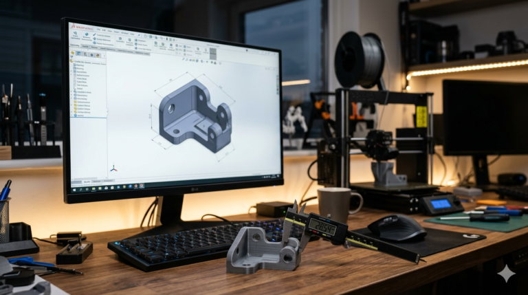
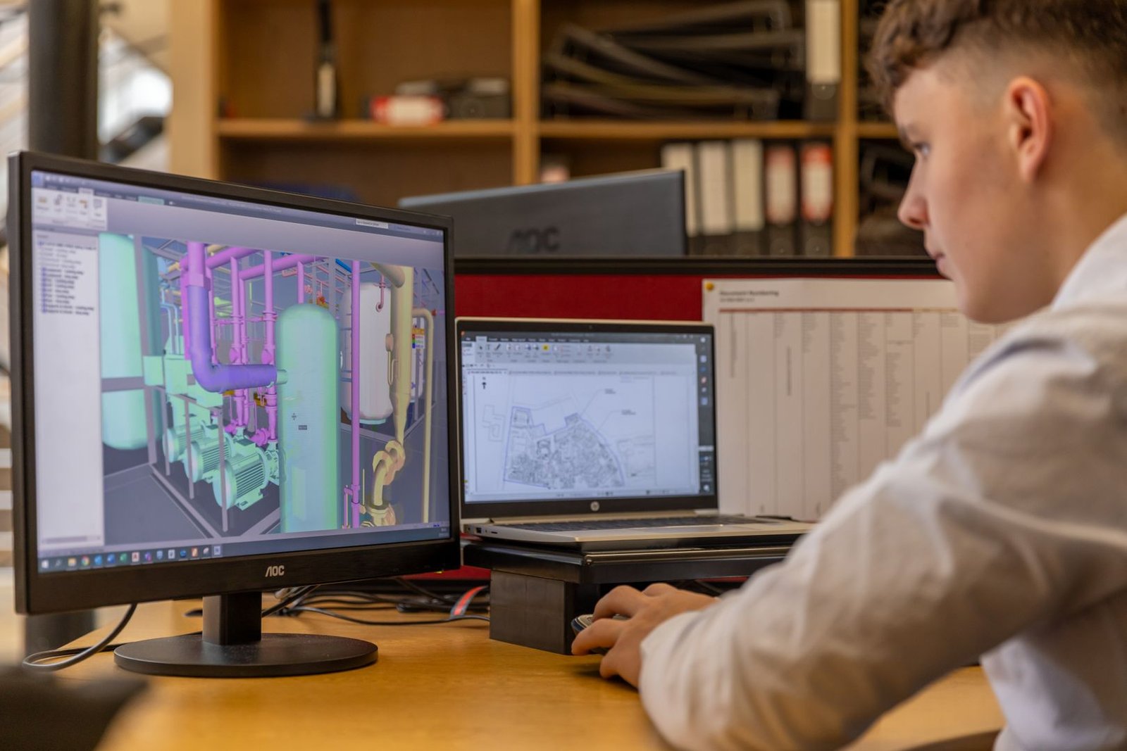
In SolidWorks we build every waterproof 3D printed enclosure as a single multibody part and split it at the seam, so the groove and its landing are guaranteed to match — modeling two separate bodies invites a 0.2 mm mismatch that leaks. The gasket is a swept solid on the groove path, used to check compression and interference before anything is printed.
Then we test physically: seal the box empty, submerge it under 300 mm of water for 30 minutes, and watch for bubbles at the seam and the glands. A faster screen is 0.2 bar of internal air with soapy water brushed over the seam. Both take fifteen minutes and prevent a recall. Our walkthrough on designing 3D printed cases and enclosures covers the base geometry this guide seals.
Ready to turn your idea into a 3D CAD model? MiniCAD has delivered 7,000+ orders over 9+ years, rated 4.9 out of 5 across 4,470+ Fiverr reviews.
Packages start at $79. Send your sketch, photo or sample through our quote form and get a personal quote within 24 hours. You pay only after you accept it. Questions? Email contact@minicad.io.