You modeled a bracket as a thin extruded solid, sent the STEP file to a fabricator, and got back a quote three times higher than expected — or a polite refusal. That is the first lesson in sheet metal design in SolidWorks: a 1.5 mm wall bent into an L shape is not a sheet metal part. It carries no bend radius, no corner relief, and no flat pattern, so nobody can cut it or fold it. This guide covers what must be correct before a press brake operator can touch your part.
Why Sheet Metal Design in SolidWorks Is Not Solid Modeling
A fabricated part is made from one flat blank that gets cut, then folded. The shop needs two things: a flat outline to cut, and a bend schedule to fold. A generic solid gives them neither. Build the part with Insert > Sheet Metal > Base Flange and SolidWorks adds a Sheet-Metal feature storing thickness, bend radius, and K-factor, plus a suppressed Flat-Pattern feature at the bottom of the tree. That Flat-Pattern is the deliverable. Everything else is presentation.
If you inherited a solid model from a client, do not remodel it from scratch. Convert to Sheet Metal lets you pick a fixed face and the bend edges, and it rips the corners for you. It fails on geometry with non-uniform wall thickness — which is exactly the diagnosis you want, because a fabricator would have rejected it too.
Set Thickness, Bend Radius, and Relief First
Pick a real stock gauge before you draw anything. Sheet stock runs roughly 0.61 mm to 6.35 mm, and shops hold specific thicknesses — 1.0, 1.5, 2.0, 3.0 mm in 5052-H32 aluminum, or 16 gauge (1.52 mm) cold rolled steel. A 1.7 mm wall exists only in your model; it will be re-quoted at the next thickness up, or the job stops for an email.
Set the default inside bend radius equal to the material thickness. It is what a standard V-die produces on most gauges and it keeps the flat pattern honest. Then set auto relief to Rectangular with a ratio of 0.5, which gives a relief width of half the thickness and a depth past the bend tangent. Without relief, the material tears at the corner where two bends meet, and the shop will add a relief of their own choosing — changing your flat dimensions without telling you.
A Sheet Metal Bend Radius Guide for Real Tooling
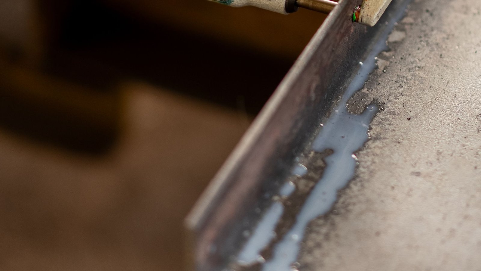
Any sheet metal bend radius guide worth following starts with the alloy, not the CAD default. Soft aluminum and mild steel bend cleanly at an inside radius of 1× thickness. Hardened alloys do not: 6061-T6 cracks on the outer fiber below roughly 2–3× thickness, which is why bent enclosures are usually 5052-H32 and machined brackets are 6061. If a client insists on 6061-T6 with a tight fold, the honest answer is to change the alloy or split the part.
Two more limits decide whether a design is buildable. Bend across the rolling grain wherever possible — bending parallel to it doubles the cracking risk on the outside of the radius. And keep every flange at least 4× thickness plus the radius. On 1.5 mm sheet with a 1.5 mm radius, that is about 7.5 mm of flange. Anything shorter drops into the die and comes out at the wrong angle.
How K-Factor Changes Your Flat Pattern
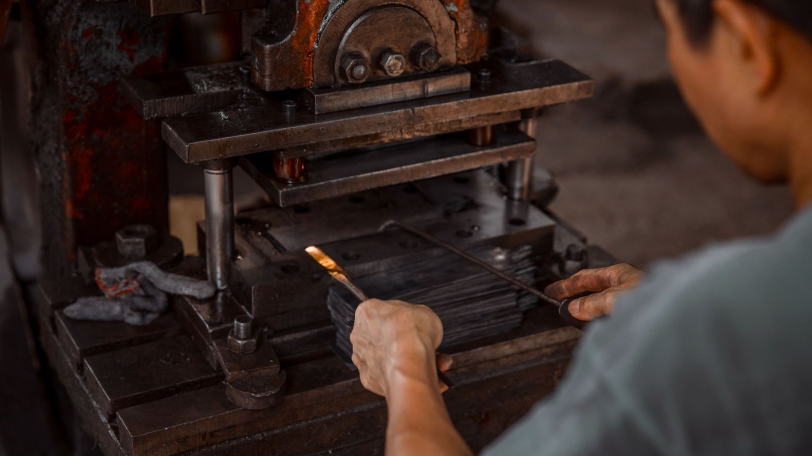
K-factor is where a good model quietly becomes a wrong part. It is the position of the neutral axis inside the material, expressed as a fraction of thickness, and it decides how much stock a bend consumes. SolidWorks ships with 0.5. Real air bending on aluminum and mild steel lands nearer 0.42–0.45.
Work it through. A 90° bend in 1.5 mm sheet with a 1.5 mm inside radius has a bend allowance of (π/2) × (R + K × t). At K = 0.44 that is 3.39 mm; at K = 0.5 it is 3.53 mm. The 0.14 mm gap looks like nothing until you count bends — a six-bend chassis accumulates roughly 0.85 mm of error, enough to miss a mounting hole pattern outright. The fix takes five minutes: ask the shop for their bend deduction or gauge table and load it in the Sheet-Metal feature. Any fabricator that cannot supply one is guessing, and so are you. Correct k-factor sheet metal SolidWorks settings are the single highest-value habit in sheet metal design in SolidWorks, because every downstream dimension inherits them.
Hole and Slot Placement Near Bends
Holes near a bend deform into ovals as the material stretches. Keep the edge of any hole at least 2.5× thickness plus the bend radius away from the bend tangent line — 5.25 mm on 1.5 mm material with a 1.5 mm radius. Hole diameter should be at least one material thickness for punching; a laser will cut smaller, but the wall taper starts to matter below that.
Tolerance across a bend is the second trap. Typical shop tolerance is about ±0.13 mm edge to edge on one face, but bend-to-hole opens to ±0.38 mm on thin material and roughly ±0.76 mm across three or more bends, as published in Protolabs’ sheet metal design guidelines. So dimension critical features from a single surface. If two holes must line up precisely, put them on the same face — never on opposite sides of a fold.
Exporting a Flat Pattern DXF for Laser Cutting
Producing a flat pattern DXF for laser cutting takes three steps. Unsuppress Flat-Pattern, right-click the flat face and choose Export to DXF/DWG, then in the export dialog select Sheet Metal and tick bend lines and forming tools so they land on their own layers. Export 1:1 in millimeters with no dimensions, no title block, and no construction geometry — a cutting file holds cut geometry only.
Do not offset for kerf. The cutting machine compensates automatically, and a designer-added offset lands the part 0.2 mm undersize on every edge. Send the DXF together with a real fabrication drawing showing bend directions, angles, hardware callouts, and finish, because bend lines alone do not say up or down. Our technical drawing service exists for exactly this handoff.
Sheet Metal Design for Manufacturing — the Real Cost Drivers
Sheet metal design for manufacturing is mostly about setups, not material. Cutting is cheap and fast; every distinct bend is a brake setup, and every unusual angle is a tool change. Standardize on 90° folds, reuse one bend radius across the whole part, and merge two shallow bends into one wherever the geometry allows. Cutting a six-bend housing down to four often saves more than switching alloys.
Three habits keep quotes low. Stay inside common sheet limits — around 990 × 1194 mm — so a part does not force an oversized blank. Use PEM-style press-in hardware instead of welded nuts or tapped holes in thin stock. And send the STEP file, the flat DXF, and the drawing in one package. Half the delays we see in SolidWorks modeling work are not design problems; they are missing files.
Ready to turn your idea into a 3D CAD model? MiniCAD has delivered 7,000+ orders over 9+ years, rated 4.9 out of 5 across 4,470+ Fiverr reviews.
Packages start at $79. Send your sketch, photo or sample through our quote form and get a personal quote within 24 hours. You pay only after you accept it. Questions? Email contact@minicad.io.