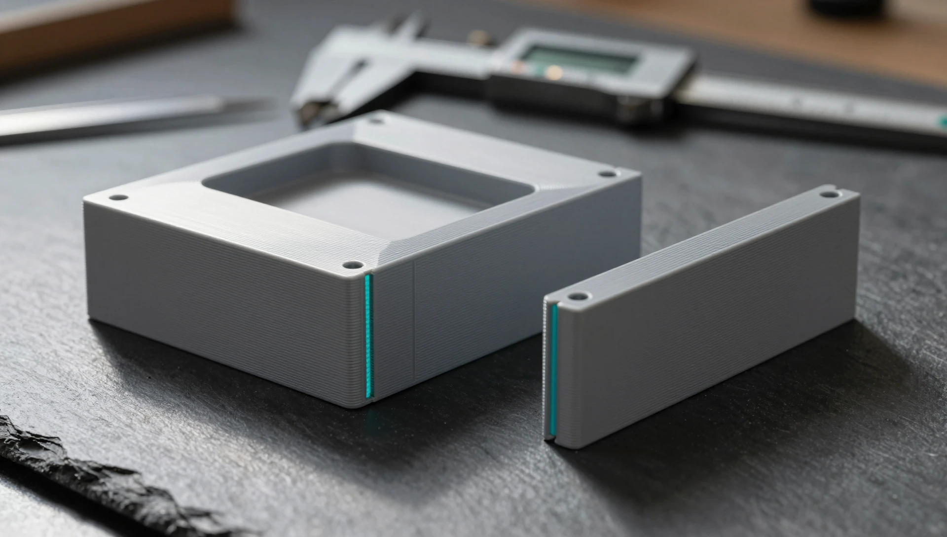
Your part measures 340 mm and your printer bed is 220 mm. Scaling it down is not an option, so you need to know how to split a 3D model for printing and rejoin the halves without a weak, misaligned seam. Done well, a split part is almost indistinguishable from a single print. Done badly, it fails at the glue line the first time it carries load.
We split parts most weeks — instrument enclosures, jigs longer than the bed, drone frames. Below is the workflow we use in SolidWorks, with the numbers we settled on after several thousand printed parts.
Why Splitting Beats Scaling the Part Down
Scaling changes every dimension at once. Mounting holes stop matching real hardware, wall thickness drops under the nozzle minimum, and press fits go loose. Shrink a part 15 percent and a 3.0 mm wall becomes 2.55 mm — still printable, but the M3 screw boss now has a 2.55 mm collar and it splits the moment you drive the screw. Standard hardware does not scale with your model.
Splitting keeps every dimension exact. You pay two costs: a seam that stays visible unless you finish it, and a joint weaker than solid material unless you design it. Both have known answers. Scaling has none.
Before cutting, check one cheaper option. A 220 × 220 mm bed offers roughly 300 mm across the diagonal. If your part is 260 mm and slim, rotate it 45 degrees in the slicer and the split disappears. That check takes thirty seconds.

How to Split a 3D Model for Printing in SolidWorks
SolidWorks handles this natively with the Split feature, which cuts one solid into multiple bodies saved as separate part files. The sequence is short.
First, take your real build volume and subtract 5 mm on each axis — printers rarely deliver the advertised envelope once a skirt and bed-leveling variation are accounted for. Second, create a reference plane exactly where you intend the cut. Third, run Insert > Features > Split, select that plane as the trimming tool, and check both resulting bodies. Fourth — the step people skip — add the joint geometry to each body before you export anything. Fifth, use Save Bodies to write each body to its own part file, then export as STL or 3MF.
Work in the solid model, never the mesh. Cutting an STL in a mesh editor gives you two open shells that need repair, and you lose the history that lets you move the cut 10 mm when the first test print puts the seam in a bad place.
Where to Place the Cut When Splitting Large Parts for 3D Printing
Cut placement decides how strong and how ugly the finished part is. Five rules cover almost every case.
Cut through the thickest available cross-section — bonded joints fail by area, so a seam through a 6 mm rib is worth far more than one through a 2 mm wall. On load-bearing joints we aim for at least 400 mm² of bonded surface. Never cut through a fillet, a hole, or a thin feature; that creates a knife edge that will not print cleanly and cannot be glued. Put the seam where the geometry already breaks: a step, a parting edge, the underside. Keep it out of tension and peel — a glue line is strongest in shear, weakest when pulled open at an edge. And choose a cut that leaves both halves a large flat face, because two well-planted halves need fewer supports than one awkward whole.
Designing a Dovetail Joint for 3D Printed Parts
A flat butt joint relies entirely on adhesive. A dovetail joint for 3D printed parts adds mechanical interlock, so the bond carries shear rather than tension and the halves cannot slide apart under load.
Our working numbers on FDM with a 0.4 mm nozzle: a dovetail angle of 10 to 15 degrees, a depth of at least 8 mm, and 0.15 to 0.20 mm of clearance per mating face. Tighter than 0.15 mm and the halves bind or crack; looser than 0.25 mm and the joint rattles with a thick, brittle glue line. Add a 0.5 mm chamfer on every leading edge so the tail starts into the socket without shaving material. Our guide to tolerances and clearances for 3D printing explains how to calibrate those figures for your own machine.
Print a 25 mm test coupon of the joint alone before committing to a six-hour print. Ten minutes of filament has saved us far more than that.
Alignment Pins for 3D Printed Assemblies
Even with a dovetail, use pins. Alignment pins for 3D printed assemblies do two jobs: they hold the halves in register while the adhesive cures, and they stop the seam stepping where it is most visible.
Use two pins minimum, spaced asymmetrically so the halves assemble only one way — a symmetric pair invites a 180-degree mistake that shows up after the glue sets. Printed pins work at 4 to 5 mm diameter with the hole 0.25 mm oversize. For structural parts, switch to a 3 mm steel dowel with a 3.1 mm hole; it is stiffer than any printed pin and costs pennies. Chamfer each hole 0.5 mm at 45 degrees so the pin self-locates.
Gluing 3D Printed Parts Together for an Invisible Seam
Adhesive choice depends on the material, but gluing 3D printed parts together is mostly surface preparation. Scuff both faces with 240-grit paper and wipe with isopropyl alcohol — a glossy printed face bonds poorly.
For PLA and PETG, medium-viscosity cyanoacrylate sets in roughly 30 seconds and reaches full strength in 24 hours — fast, but with no repositioning time, which is why the pins matter. For structural joints use 30-minute two-part epoxy: the longer open time lets you seat the halves properly and it holds far better under peel. For ABS, an acetone slurry made from ABS scrap chemically welds the parts and beats any adhesive.
Keep the glue line thin — clamp lightly, do not flood the joint. To hide the seam, fill it with filler primer, sand 240 then 400 grit, and prime again. Two cycles usually make it invisible under paint.

Mistakes That Ruin a Split Part
Five recur every time someone works out how to split a 3D model for printing. Cutting the STL instead of the solid, leaving non-manifold shells. Zero clearance, because geometry that mates on screen will not physically assemble. Forgetting to mirror the joint — a tail on both halves fits nothing. Seaming across a load-bearing fillet, putting the weakest line where stress concentrates. And printing both halves in the same orientation out of habit, when each usually has its own best flat face.
A Short Checklist Before You Slice
Confirm the diagonal trick will not save you the split. Verify each half fits the build volume minus 5 mm. Confirm the joint has clearance, a chamfered lead-in, and at least two asymmetric pins. Check each half has a flat face to print on. Export from the solid model, not the mesh, and open each STL in your slicer to confirm it is watertight. Our STL file design service handles this sequence when a part has to be right the first time.
Ready to turn your idea into a 3D CAD model? MiniCAD has delivered 7,000+ orders over 9+ years, rated 4.9 out of 5 across 4,470+ Fiverr reviews.
Packages start at $79. Send your sketch, photo or sample through our quote form and get a personal quote within 24 hours. You pay only after you accept it. Questions? Email contact@minicad.io.