You have modeled every individual part. Each component opens cleanly in SolidWorks. But the moment you bring them together, something breaks — the housing doesn’t mate flush, a screw axis is off by half a degree, or the cap interferes with the inner flange. SolidWorks assembly design is where mechanical products actually come to life, and it demands a different mindset from single-part modeling. This guide walks through the complete workflow — from first component insertion to a BOM-ready handoff package — drawing on techniques refined across 7,000+ delivered SolidWorks projects.
What Is SolidWorks Assembly Design
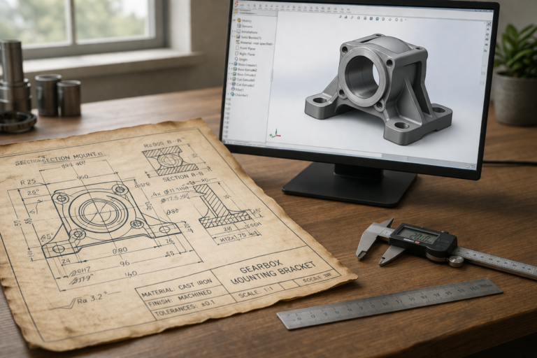
A SolidWorks assembly (SLDASM file) references multiple part files and positions them relative to each other using geometric relationships called mates. Unlike a multi-body part file — where all geometry shares a single environment — an assembly keeps each component in its own separate, fully editable SLDPRT file. That distinction matters in manufacturing: your machinist receives the individual part file, not a merged solid. Assemblies are also the correct environment for interference checks, motion simulation, Bills of Materials, and exploded-view drawings.
Two fundamental approaches define SolidWorks assembly design: bottom-up and top-down. Most professional contract work starts bottom-up.
Bottom-Up Assembly in SolidWorks
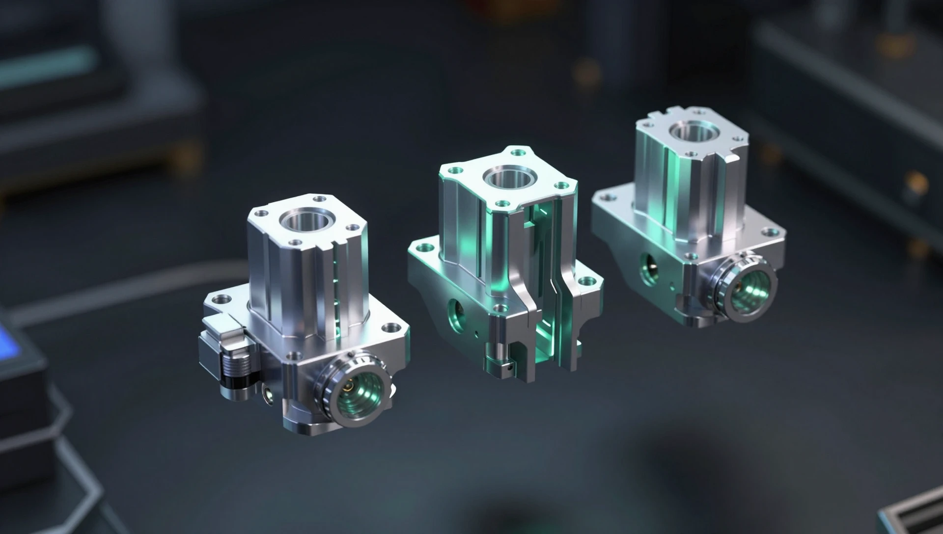
In a bottom-up workflow, every component is fully modeled before it enters the assembly. You insert parts via Insert → Component → Existing Part/Assembly, then apply mates to constrain them. The first component you drop in is fixed (grounded) by default — it becomes the reference frame. Every part added after that floats freely until mates define its position.
Bottom-up is the professional standard for contract CAD work because each part file is independent. If the client revises the housing geometry, you update that single SLDPRT and the assembly regenerates automatically. For teams with multiple designers working in parallel, bottom-up also eliminates in-context references — a common source of broken files when one designer renames or relocates a component. Start here unless tight spatial packaging demands the reverse approach.
SolidWorks Assembly Mates: The Core of Constraint
Mates are the rules that position components. SolidWorks resolves them in real time and flags any over-constrained relationship with a red warning icon. The six mates you will use on virtually every project:
- Coincident — two faces, edges, or points share the same plane or axis. This is the workhorse mate for flush surfaces and axial alignment.
- Concentric — two cylindrical surfaces share the same central axis. Use this for bolts in holes, shafts in bearings, and any cylindrical fit.
- Distance — a measured gap between two entities. Essential for clearance-critical fits and standoff geometry.
- Parallel — two planes or edges remain parallel without forcing them to touch.
- Angle — constrains the angular relationship between two faces. Critical for hinges, rotating brackets, and angled mounting surfaces.
- Width Mate — centers a tab symmetrically between two parallel faces in a single operation, replacing two coincident mates.
A fully constrained component shows zero degrees of freedom in the FeatureManager. Leave exactly one rotational DOF free on any part intended for motion simulation — fully locking a shaft prevents SolidWorks Motion from animating it. Over-constraining is the most common assembly error; if a mate turns red on creation, delete it and inspect which existing mate already defines that relationship. The SolidWorks documentation categorizes all mate types and lists which combinations cause over-constraint.

Top-Down Assembly Design: When It Makes Sense
Top-down design reverses the order: you create parts inside the assembly environment, driven by a master layout sketch or by references to existing geometry. The classic use case is an ergonomic enclosure that must wrap precisely around a PCB. You reference the board outline to drive wall offsets, and any future PCB revision propagates to the enclosure automatically — no manual re-dimensioning.
The trade-off is fragility. In-context references create external links (noted by the “->” suffix in the FeatureManager) that break if a referenced file is renamed or moved. Use top-down selectively — only where dimensional coupling genuinely eliminates rework. For loosely related components with fixed dimensions, bottom-up is faster, easier to share, and more predictable when the project changes hands.
Interference Detection: Find Clashes Before You Manufacture
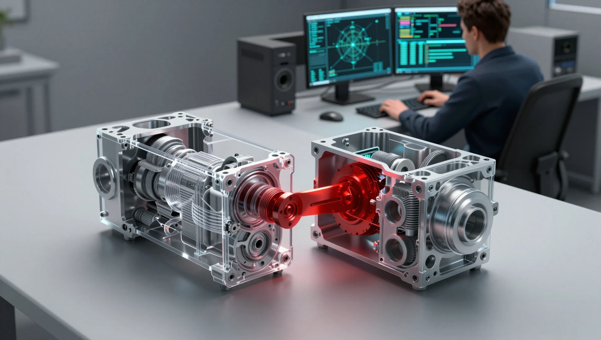
Interference detection lives under Tools → Evaluate → Interference Detection. Select all components, click Calculate, and SolidWorks highlights every volumetric overlap in red and reports each interfering pair with the volume of intrusion in cubic millimeters.
Run it at three checkpoints: immediately after initial mating (catches gross geometry errors), after applying all mates (catches assembly-level clashes), and after any design revision. A 0.2 mm wall penetration at a cap-to-housing joint is invisible in an isometric view but will trigger a reject at incoming inspection. Finding it digitally costs a click; finding it after a first article costs a remachining cycle or a new tool. For assemblies destined for FDM 3D printing, also run Clearance Verification — FDM tolerances are typically ±0.2–0.4 mm, and a fit designed for machined steel will bind when printed in PLA or PETG.
SolidWorks Assembly Best Practices That Save Time
Large assemblies with hundreds of components slow regeneration significantly. SolidWorks provides Lightweight Mode — right-click any component and select Set to Lightweight — which loads only the geometry needed for display, deferring full model data until that component is actively edited. For assemblies above roughly 50 parts, enable Large Assembly Mode under Tools → Options → Assemblies. This automatically activates SpeedPak and other memory-saving features.
Naming conventions matter more in assemblies than in part files. A component named “Part3” in a 40-part assembly is meaningless six months later. Name descriptively from the start: “housing-top”, “lid-cap-m3-boss”, “bracket-left-8mm”. Organize mates by component in the FeatureManager using mate folders — this cuts debugging time dramatically when a downstream geometry change causes a mate to fail and you need to locate the culprit quickly.
Before any client delivery, run File → Find References to confirm all referenced part files are present and correctly linked. A broken reference on the client’s machine renders as a red X on that component — a preventable error that undermines confidence in the entire file package.
Exploded Views, BOMs, and Drawing Handoff
An exploded view separates each component outward along a defined axis to illustrate assembly sequence. Create one via Insert → Exploded View, then define explode steps by dragging components along their dominant direction. SolidWorks records each step, enabling animated collapse and expand for presentations and assembly manuals.
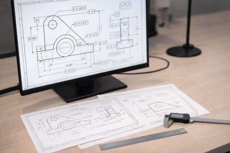
The Bill of Materials generates automatically from the assembly file: insert a BOM table in a drawing view and SolidWorks populates item numbers, part names, quantities, and any custom properties assigned to each SLDPRT. Balloon annotations link BOM rows directly to components in the exploded drawing. This is the standard contract manufacturing handoff — assembly drawing, BOM, and individual part drawings, all derived from the same SLDASM file with no manual transcription and no risk of a mismatch between drawing and model.
For an in-depth look at individual part modeling that feeds into this workflow, see 3D Modeling in SolidWorks — The Complete Professional Reference.
If your project requires professional SolidWorks assembly design — SLDASM file, individual part files, technical drawings, and BOM — MiniCAD delivers it in 24 hours. With 7,000+ projects completed across 40+ countries and a 4.9★ rating from 4,470+ verified reviews, our assemblies go directly to manufacturing without revision loops. Get a quote or reach us at contact@minicad.io.