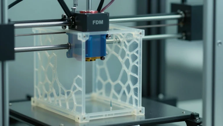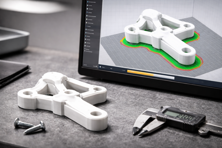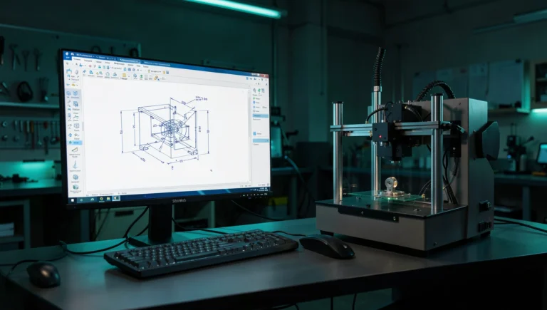
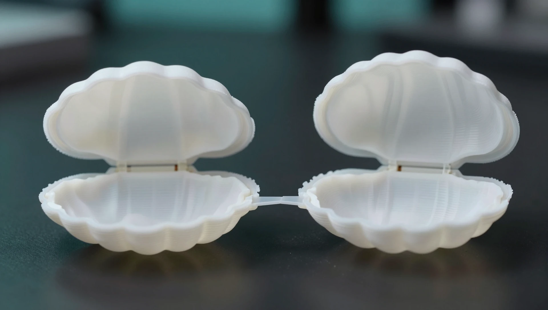
A one-piece lid that folds shut looks trivial on screen and cracks on the third open. Living hinge design for 3D printing is the most underestimated feature we see in client files: a thin web drawn in ten seconds, printed in the wrong orientation, broken before delivery. The geometry is not the hard part. The hard part is that an FDM printer builds that web from stacked layers, and a hinge bending across layer lines is pre-cracked. Here are the decisions that make one survive.
Why Printed Hinges Fail Before the Tenth Cycle
An injection-molded polypropylene hinge survives a million cycles because the molecular chains align across the hinge as molten polymer fills the mold. That alignment carries the bending stress. An FDM printer does the opposite: it lays down beads that bond by partial remelt, and interlayer bond strength typically reaches only 40 to 70 percent of the strength along the bead. Bend a hinge whose layer lines cross the fold and you load the weakest interface in the part in tension.
The second driver is material. PLA yields at roughly 1 to 2 percent strain and then fractures, while a 0.4 mm web folded 180 degrees sees far more. This is not a printing defect. PLA cannot do this job.
Living Hinge Design for 3D Printing Starts With the Web
Every reliable hinge we have modeled shares four traits, and living hinge design for 3D printing fails without all four. Keep the web thin and the span long: 0.3 to 0.5 mm thick, 2 to 4 mm long along the bend direction. A longer web spreads the same rotation across more material and cuts peak strain roughly in proportion to its length. Blend the web into the thick walls with R0.8 to R1.5 fillets on both faces, and taper the wall down over 2 to 3 mm instead of stepping — a sharp step from a 2.5 mm wall to a 0.4 mm web is a stress riser and the usual crack origin. Run the hinge as one continuous band across the full width; splitting it into short tabs multiplies free edges, and free edges initiate cracks.
These sit inside the broader 3D printing design rules for engineers, but the hinge is the one feature where breaking a rule fails immediately rather than gradually.
3D Printed Living Hinge Thickness That Survives
The right 3D printed living hinge thickness is a slicer decision as much as a CAD decision. With a 0.4 mm nozzle, a 0.4 mm web resolves as a single extrusion width — one continuous bead per layer, no bond line down the middle. Model 0.45 mm and the slicer may produce two thin walls with a weak seam between them, worse than either 0.4 or 0.8 mm.
Our working numbers: 0.4 mm for lids and clamshell cases up to about 120 mm wide, 0.3 mm for small parts needing a light closing force, 0.5 mm when the hinge must also hold the lid open. Below 0.25 mm the web prints inconsistently and tears. Above 0.6 mm the bend radius grows, outer-fiber strain climbs, and the hinge whitens and fails sooner. Do not guess — print a 40 by 25 mm test piece carrying three webs at 0.3, 0.4 and 0.5 mm, fold each fifty times, and keep the one that is not whitening.

Best Material for Living Hinge 3D Printing
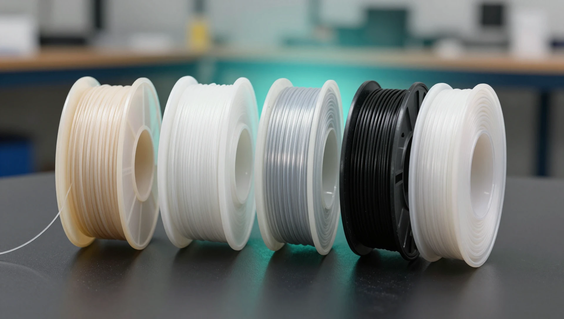
Material moves cycle life by two orders of magnitude — it outweighs every other decision here. Honest expectations from our own test pieces, folded to 180 degrees: PLA fails under 20 cycles and should never be used. PETG reaches roughly 200 to 500 cycles, acceptable for a demo unit. ABS lands in a similar range with a softer failure mode. Nylon PA12 passes several thousand cycles and is the practical choice for functional prototypes. Polypropylene is the correct answer when the hinge must last, holding up past 10,000 cycles because it cold-draws instead of cracking. The catch is that PP warps aggressively and only sticks to PP packing tape or a dedicated PP sheet, so plan the bed surface first.
TPU 95A flexes indefinitely but is too soft to hold a lid in position, so use it only where the hinge is a tether. Before cutting a mold, a fatigue study in SOLIDWORKS Simulation will find the stress concentration at the fillet — but it cannot predict interlayer failure. Only a physical print does that.
Print Orientation Decides the Cycle Life
This single change turns a hinge from disposable to usable. Print the part flat and fully open, hinge lying in the build plane, axis parallel to extruder travel. The perimeter beads then run along the hinge axis, so bending stress stays inside continuous filament instead of crossing bead-to-bead bonds. Print the same part standing up and the fold loads pure layer adhesion — expect failure on the first or second cycle in any material.
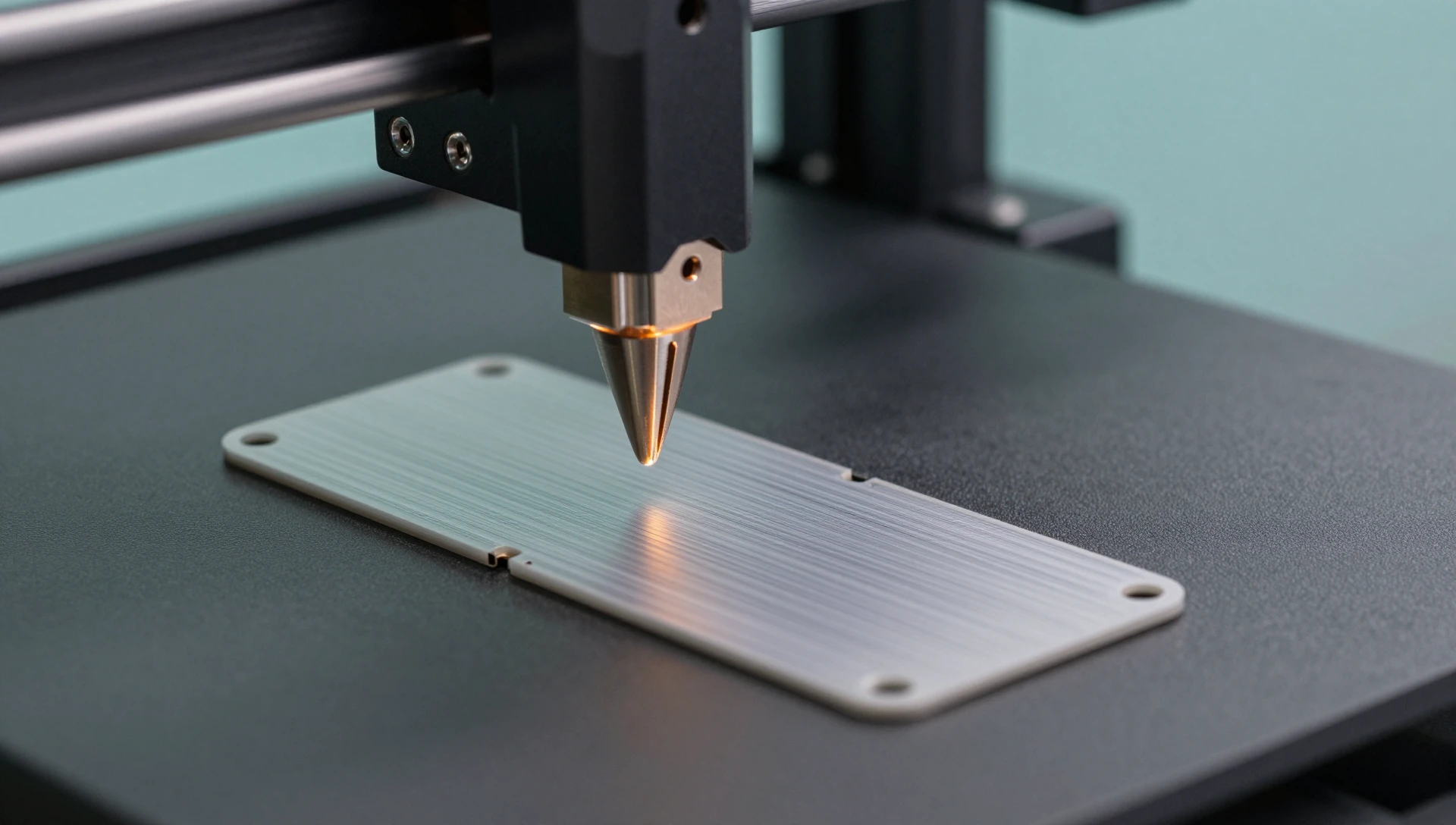
Back that orientation with four settings: a 0.15 to 0.2 mm layer height so the web is two or three well-bonded layers, 20 to 25 mm/s over the hinge region, a nozzle 10 °C above normal for better interlayer welding, and part cooling off over the hinge layers. Then flex the hinge 20 to 30 times right after printing, while it is still warm — the same cold-drawing molders exploit extends life on PP and PA12.
Polypropylene Living Hinge Design in SolidWorks
Model the hinge as an explicit feature, never as a byproduct of a shell. Build the two rigid bodies first, then cut the web with a single sketch driven by a global variable such as hinge_t, so a thickness change propagates through the fillets and the taper in one rebuild. Polypropylene living hinge design benefits most from this, because PP shrinks 1.5 to 2.5 percent and you will iterate the web at least twice.
Add fillets last, in a separate feature at the end of the tree, so they can be suppressed for a fast test print. Keep the hinge sketch fully defined and dimension the web directly rather than deriving it from an offset — offsets drift when upstream geometry moves. That discipline is standard in our SolidWorks modeling work: a client changes one number and re-exports a print-ready STL without rebuilding the model.
When Flexible Joint Design for 3D Printed Parts Beats a Hinge
A living hinge is not always right, and flexible joint design for 3D printed parts offers three alternatives worth costing first. Above roughly 5,000 cycles in anything other than PP, switch to a printed pin-and-barrel hinge: interleaved knuckles with 0.35 mm radial clearance and a separate steel or printed pin. It lasts effectively forever and prints in any material. Where the joint must seal, a two-material print with a TPU band bridging two rigid halves delivers flex and gasket in one operation. And when the product is heading to injection molding, design the true PP hinge for the mold but use pin-and-barrel for the prototypes — a printed hinge will never represent the molded one honestly.
Get the Hinge Right on the First Print
A hinge that fails is rarely a printing problem. It is a geometry, material and orientation decision made three steps earlier.
Ready to turn your idea into a 3D CAD model? MiniCAD has delivered 7,000+ orders over 9+ years, rated 4.9 out of 5 across 4,470+ Fiverr reviews.
Packages start at $79. Send your sketch, photo or sample through our quote form and get a personal quote within 24 hours. You pay only after you accept it. Questions? Email contact@minicad.io.