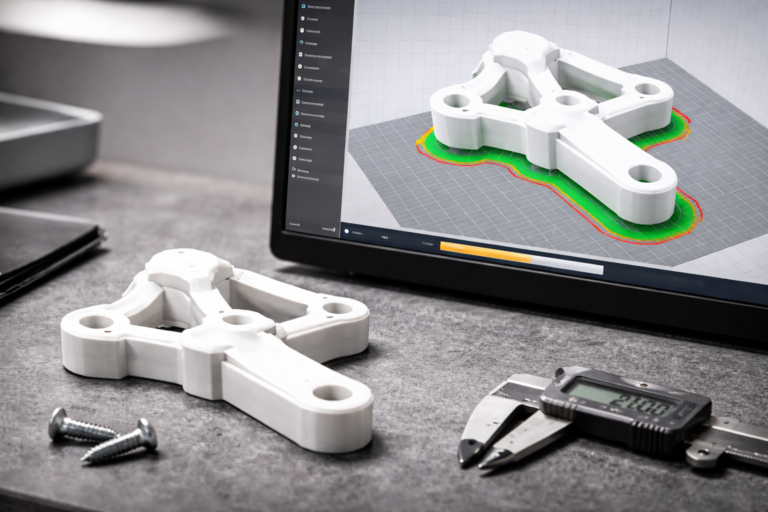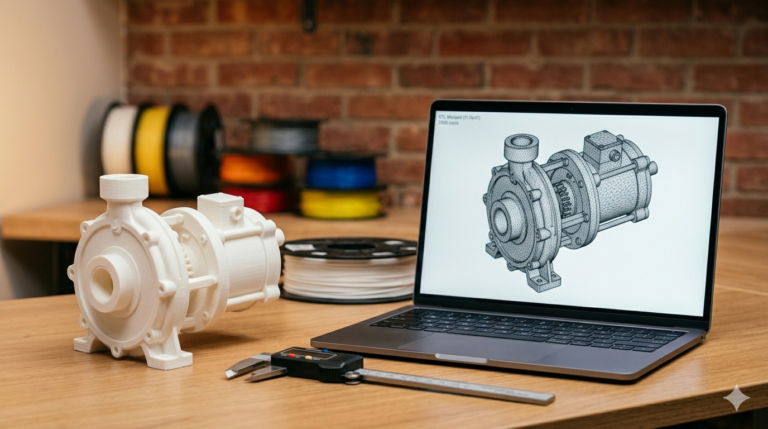
Every week, clients send us a photograph of a hand sketch and ask whether it is enough to 3D print. It almost never is — but a drawing for 3D printing is not a single thing. Depending on where you are in the design process, it is either the 3D model file a printer reads directly, or a 2D engineering drawing that tells the modeler exactly what to build. Knowing which one you need — and what it must contain — is the difference between a part that fits on the first try and one that gets reprinted three times.
What Drawing for 3D Printing Actually Means
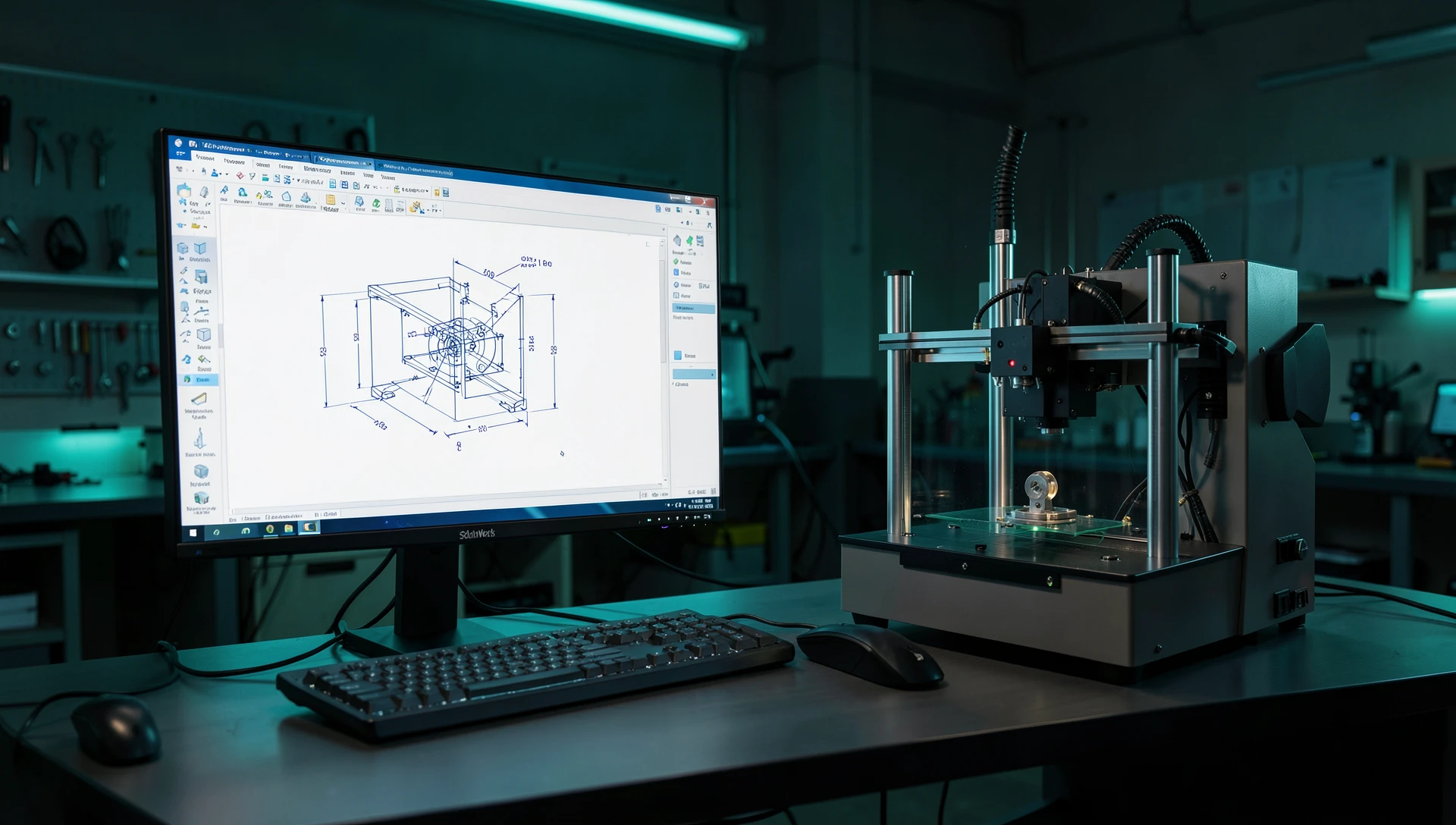
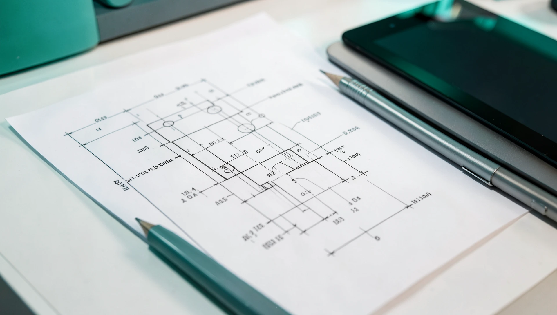
The phrase covers two distinct deliverables that are frequently confused. The first is the print file — most commonly an STL or STEP — which encodes the 3D geometry of the part. A printer or slicing program reads this file directly; it contains no dimensions or tolerances, only surface data. The second is the technical drawing — a 2D document produced in SolidWorks or similar software — that annotates the geometry with dimensions, tolerances, material callouts, and surface finish requirements. Both can be called a “drawing for 3D printing,” but they serve completely different purposes. If you are placing an order with a print service, you typically need the first. If you are commissioning a CAD designer to build the model for you, you typically provide the second as your reference document.
When a 3D Model File Is All You Need
For most consumer and prototyping orders, an STL or STEP file covers everything the printer requires. STL encodes the surface as a mesh of triangles — compact, universally accepted, and the default export from virtually every CAD package. STEP (specifically ISO 10303-21) encodes precise parametric geometry, which matters when the part will also be used for CNC machining or injection molding downstream. If your use case is a one-off prototype, a display model, or a functional part without critical fits, a clean STL at the correct units (millimeters, not inches) is sufficient. Export resolution matters: an STL produced at too-coarse a setting will show faceting on curved surfaces. In SolidWorks, a deviation tolerance of 0.005 mm and an angular tolerance of 0.5° gives smooth curves without bloating file size.
When a Technical Drawing for 3D Printing Is Required
A technical drawing for 3D printing becomes essential the moment tolerances matter. FDM printing holds ±0.3–0.5 mm on consumer machines; resin SLA holds ±0.05–0.1 mm on a well-calibrated system. If your part must mate with a shaft, snap into a housing, or pass through a hole in another component, the drawing is where you specify the fit — clearance, interference, or transition — so the modeler can add the correct offset before export. A drawing also captures information the 3D file physically cannot: material grade, layer orientation preference, post-processing requirements (sanding, priming, painting), and any critical dimensions that must be verified after printing. Without a drawing, a designer guesses. With one, there is no ambiguity.
What a CAD Drawing for 3D Printing Must Include
A cad drawing for 3d printing does not need to be a full GD&T blueprint. For most prototyping work, the following is sufficient:
- Overall dimensions — length, width, height in millimeters. State the unit explicitly; mixing inches and millimeters has destroyed more than one print run.
- Critical fits and hole sizes — any dimension where a mating part will engage. Call out the nominal dimension plus the tolerance, for example Ø8.0 ±0.1 mm for a clearance fit on an M8 rod.
- Wall thickness — FDM parts need a minimum wall of 1.2 mm (two perimeter passes at 0.6 mm line width) to print solid. Thinner walls vanish in slicing. Note any thin features explicitly.
- Thread specifications — M-series metric threads must be called out on the drawing; they cannot be inferred from a visual sketch.
- Surface finish requirements — “as-printed,” “sanded to 220 grit,” or “smooth enough to accept primer” are all legitimate callouts and each requires a different time budget.
- Quantity and material — PLA, PETG, ABS, TPU, or resin. If you need food-safe or UV-resistant material, state it.
A clear annotated sketch exported to PDF covers this list for most orders under $100. The more complete your drawing, the fewer revision rounds you will need.
STL File Preparation for a Print-Ready Output
Once the 3D model exists, stl file preparation is the step most clients skip — and the one that causes the most failures. Before sending a file to any print service, run it through a repair tool such as Meshmixer or PrusaSlicer’s built-in checker. Common issues: non-manifold edges (holes in the mesh), inverted normals, self-intersecting faces, and duplicate vertices. A file with these errors will either fail to slice or produce a part with internal voids. In SolidWorks, exporting to STL using “Check all” and resolving any flagged geometry before export eliminates 90% of downstream repair work. Also verify the bounding box after export — a common mistake is exporting in inches rather than millimeters, resulting in a part 25.4× too large or small in the slicer.
CAD 3D Print Workflow: From Concept Drawing to Finished Part
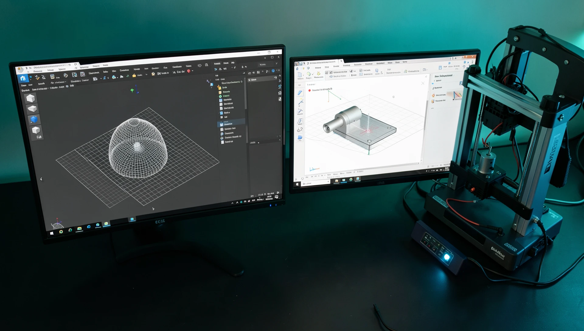
A repeatable cad 3d print workflow looks like this: (1) Produce or receive a reference drawing with all critical dimensions called out. (2) Build the parametric model in SolidWorks, applying tolerances at the sketch level so they propagate to every derived view. (3) Run a design check — confirm wall thickness, identify unsupported overhangs beyond 45°, verify threads are modeled correctly. (4) Export a STEP file for the record and an STL for the printer; both live in the same project folder. (5) Send the STL plus the 2D drawing PDF to the print service, so they have the geometry and the intent. This workflow eliminates the back-and-forth that adds days to a prototype cycle. At MiniCAD, steps 1 through 4 are what our technical drawing service covers — we deliver both the STEP model and a clean technical drawing PDF ready for manufacturing.
Common Mistakes That Cause Reprints
After 7,000+ projects, these are the errors we see repeatedly. First: submitting a 2D sketch without dimensions and expecting the modeler to guess. A professional will ask — an inexperienced one will estimate, and the part will come back wrong. Second: not specifying tolerance on mating features. A hole drawn at exactly 10 mm will print at 10.3–10.5 mm on FDM; without a callout, the designer has no guidance to compensate. Third: over-constraining the drawing with GD&T callouts that cannot be verified on a printed part — flatness to 0.01 mm, for example, is a machining spec, not a printing one. Match your callouts to what the process can deliver. The STL file design service at MiniCAD includes a pre-flight check on every submitted drawing to catch these issues before modeling starts.
Get Your Drawing for 3D Printing Right the First Time
A well-prepared drawing for 3D printing — whether a reference sketch, a formal 2D annotation, or a clean export-ready 3D file — is the single biggest variable in whether your prototype succeeds or needs another round. MiniCAD has delivered 7,000+ projects across 40+ countries, with a 4.9★ rating from 4,470+ verified clients and a 24-hour standard turnaround. If you have a concept, a sketch, or a drawing that needs to become a print-ready file, get a quote — we will tell you exactly what we need and have your file ready by tomorrow. Reach us at contact@minicad.io any time.