
Uncured resin trapped inside a hollow part will crack that part open weeks after you ship it. That single failure mode is the clearest reason resin 3D printing design rules are not FDM rules with smaller numbers — they are a different constraint set. Resin cures close to isotropic, so layer adhesion stops being the weak axis. What replaces it is trapped liquid, peel force, and cure shrinkage.
Why Resin 3D Printing Design Rules Differ From FDM
On an FDM machine you size walls in multiples of nozzle width, keep overhangs under 45 degrees, and accept a Z axis roughly 30 percent weaker than XY. None of that governs a masked-SLA printer. Every layer cures against a transparent FEP film then peels away, and peel force scales with layer cross-section. A flat 40 cm² face parallel to the plate generates tens of newtons on every layer — enough to shear thin features or tear a part off its supports.
The second difference is chemical. Photopolymer keeps reacting after the print finishes, so thick solid sections cure exothermically, shrink unevenly, and bow. The FDM instinct to add material for strength actively hurts you here. If you are still choosing a process, see our breakdown of FDM versus SLA for product prototyping. This guide picks up after that decision.
Wall Thickness for Resin 3D Printing
Correct wall thickness for resin 3D printing depends on whether both edges are supported. A wall braced by adjacent geometry prints reliably at 0.6 mm. A free-standing wall needs 1.0 mm minimum, and will still bow during post-cure if it runs past about 40 mm without a rib behind it.
The figures we work to on production parts: 2.0 mm for structural and enclosure walls, 1.5 mm for cosmetic shells, 1.0 mm as the floor for anything carrying load. Vertical pins need 0.8 mm diameter minimum — thinner and they snap during support removal, not during printing. Raised text wants 0.5 mm line width and 0.4 mm relief; engraved text 0.6 mm wide and 0.4 mm deep. Below that, detail fills with resin and vanishes.
Hollowing Models for Resin Printing Without Collapse
Do not print solid. Any section thicker than roughly 4 mm should be hollowed, for three reasons: cost, cure warp, and print time. Take an 80 × 50 × 30 mm block. Solid, that is 120 cm³ — about 132 g of resin, roughly $8 at $60 per litre. Shell it to 2 mm and it drops to 35 g, near $2. Across a 200-unit bridge run that is over a thousand dollars, and the thin shell cures without the internal stress that bows a solid block.
Hollow in CAD, not in the slicer. In SolidWorks, use the Shell feature at 2.0 mm and model the openings as real cuts. Slicer hollowing operates on the mesh, gives no parametric control, and often leaves non-manifold geometry behind. Inside any shell longer than 60 mm, add 1.5 mm ribs every 25 to 30 mm so the wall does not dent under thumb pressure.
Drain Holes for Resin 3D Printing: Size and Placement
One hole is not enough. A single opening traps air, so the cavity drains at a trickle and never empties. Use two: a 3.5 mm drain at the lowest point in the print orientation, and a 3 mm vent at the highest. Air enters through one, resin leaves through the other, and the cavity clears in seconds.
Skip this and the leftover liquid keeps polymerising inside the sealed shell. It expands, and two to six weeks later the part splits along a wall — we have seen this on parts that passed every inspection at delivery. Put the holes on a face that will be bonded, seated, or hidden, and note the orientation assumption on the drawing so nobody flips the part and defeats the placement.

Cupping and Suction Traps That Destroy Prints
A hollow part with a concave face pointed at the build plate becomes a suction cup. Each peel cycle pulls a partial vacuum inside it, and the force can exceed 100 N — far more than the supports will hold. Either the part tears free, or the film ruptures and the tank drains into the machine.
Fix it in the model. The vent hole from the previous section usually solves it outright, provided it sits inside the concavity. Where it does not, break the concave surface with a chamfered lip so no sealed pocket can form, or tilt the part so the cavity never sits parallel to the plate.
Shrinkage, Holes, and Fits in Cured Resin
Standard resins shrink 0.3 to 0.6 percent between printing and full post-cure. On a 100 mm dimension that is 0.3 to 0.6 mm — the difference between a press fit and a loose one. Apply the allowance to critical mating dimensions, or design so the critical fit is reamed rather than as-printed.
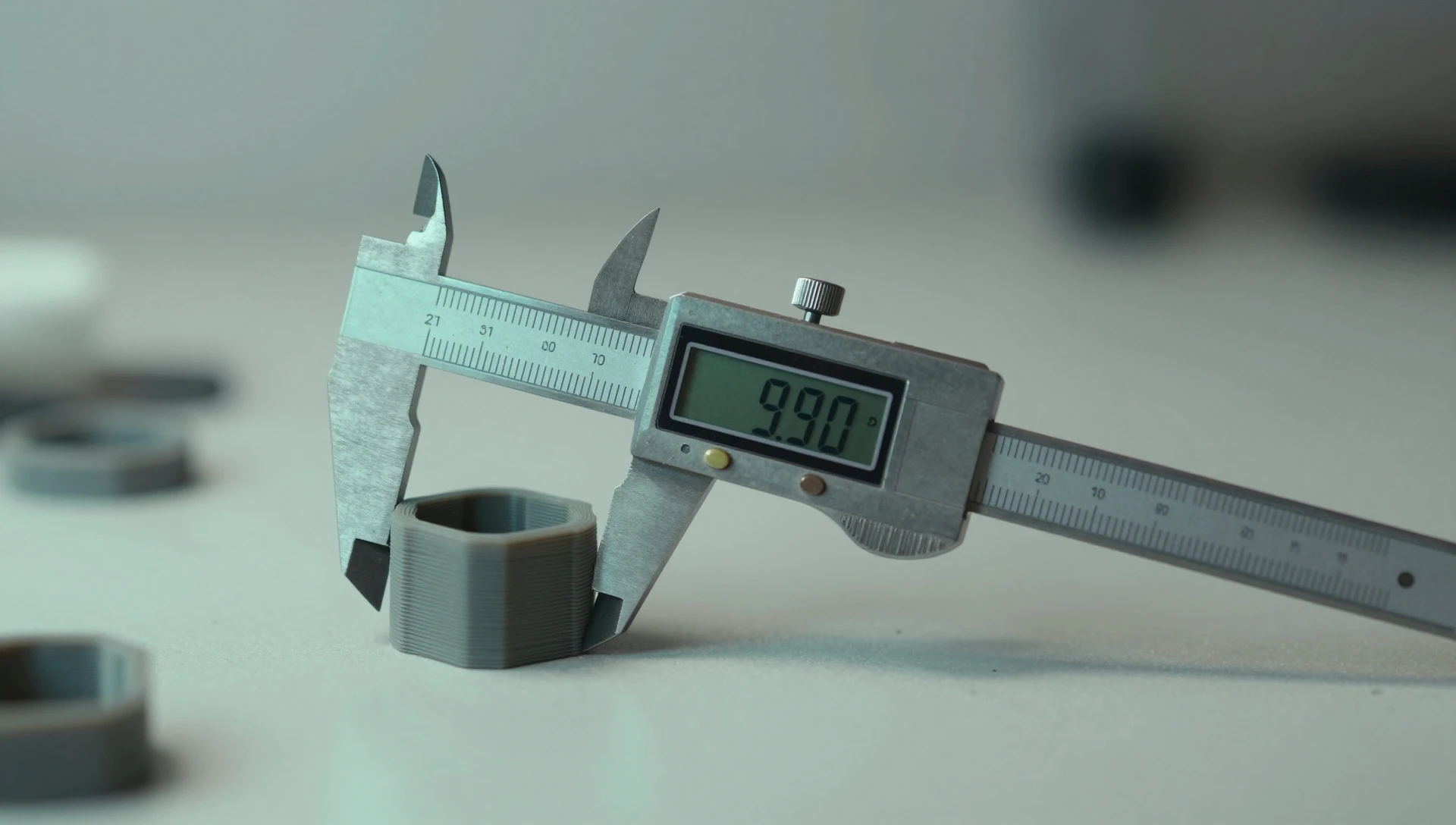
Holes come out undersize. Light bleeds through cured material and over-exposes the hole wall, so a modelled 5.0 mm hole typically measures 4.80 to 4.90 mm. Add 0.10 to 0.15 mm to hole diameters, or ream after curing. For clearance between moving parts, 0.15 to 0.20 mm per side is the working figure — tighter than the 0.30 to 0.40 mm we use on FDM, because SLA finish is smoother and layers sit at 25 to 50 µm. The first three to five layers are also overexposed for adhesion and flare outward 0.1 to 0.3 mm, so chamfer the bottom edge 0.3 mm.
SLA 3D Printing Design Guidelines for Orientation and Supports
Orientation is a design decision, not a slicer setting, and good SLA 3D printing design guidelines treat it that way. Never lay a large flat face directly on the plate. Tilt 15 to 30 degrees so peel force applies progressively across each layer, and keep the largest cross-section under roughly a third of the plate area.
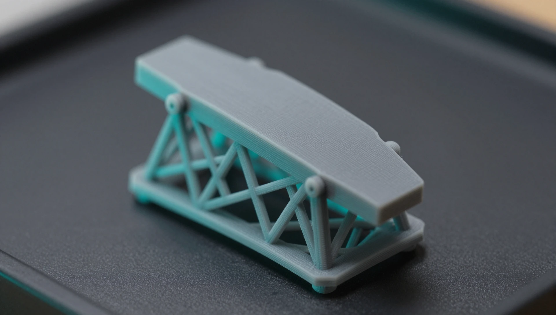
Supports leave witness marks of 0.3 to 0.5 mm. Decide during modelling which faces can carry them: sealing surfaces, optical windows, and mating flanges cannot. Where a part offers no acceptable support face, model a sacrificial pad — a 1 mm tab on a non-functional edge that supports attach to and that gets cut away afterwards. Fifteen minutes of modelling saves an hour of sanding per unit.
Exporting a Clean File for Resin Printing
Resin resolves 25 µm layers, so a coarse mesh export throws that resolution away. SolidWorks defaults to 0.05 mm deviation and a 30 degree angle tolerance, which leaves visible faceting on curved surfaces. Use Save As STL, open Options, choose Custom, and set deviation to 0.01 mm with a 5 degree angle tolerance. Confirm the mesh is watertight and manifold, keep units in millimetres, and send the STEP alongside the STL so the next engineer can edit rather than remodel. Formlabs publishes measured mechanical data worth reading during material selection — their guide to stereolithography is a solid reference. If that work is not where you want your week to go, we handle it as print-ready STL file preparation.
Applied together, these resin 3D printing design rules eliminate the three failures behind most rejected SLA parts: trapped resin, suction, and shrinkage.
Ready to turn your idea into a 3D CAD model? MiniCAD has delivered 7,000+ orders over 9+ years, rated 4.9 out of 5 across 4,470+ Fiverr reviews.
Packages start at $79. Send your sketch, photo or sample through our quote form and get a personal quote within 24 hours. You pay only after you accept it. Questions? Email contact@minicad.io.