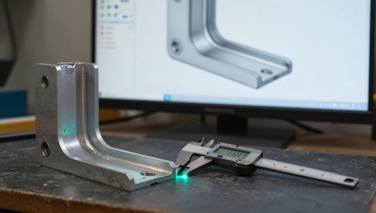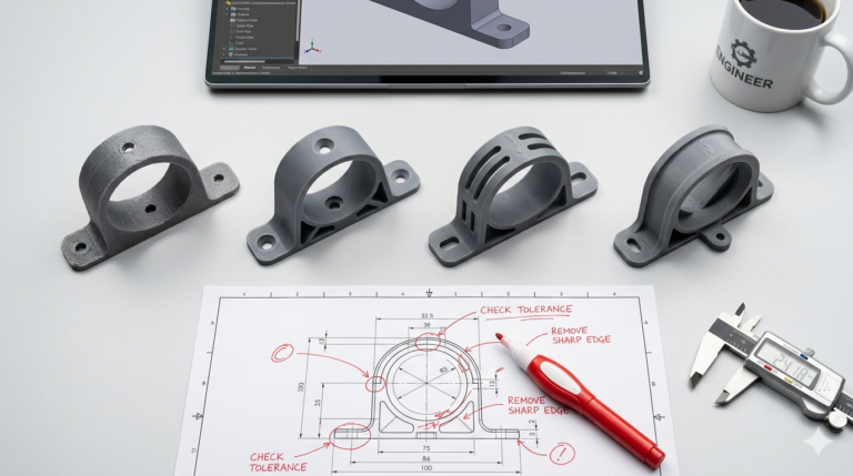

You sent a STEP file to a machine shop, and the quote came back at nearly double your estimate with three questions attached. That gap is almost always geometry, not pricing — and CNC machining design guidelines are what close it. A milling machine removes material with a round, finite tool that can only reach so far. Every feature you model either cooperates with that tool or fights it, and the fight shows up as machining time on your invoice. Here are the rules that actually change quotes on real jobs.
Why CNC Machining Design Guidelines Start With the Cutting Tool
Before any dimension matters, two things decide the cost of a machined part: how many directions the tool has to approach from, and how many times the part must be re-clamped. Each new setup means unclamping, re-fixturing, re-probing, and re-verifying — realistically 20 to 40 minutes of shop time before a single chip is cut, plus a fresh chance for misalignment.
A part that machines in two setups is dramatically cheaper than the same part with one small feature on a fifth face. When we model for milling, we ask early which faces carry features. If a boss on the underside exists only for convenience, moving it to a face already being machined removes an entire setup — usually a bigger saving than every other rule here combined.
Minimum Wall Thickness for CNC Machining
Thin walls do not break during machining — they vibrate. The tool pushes, the wall flexes away, then springs back into the cutter. The result is chatter marks, a tapered wall, and a part that measures differently at the top than at the bottom.
Working numbers we design to: for aluminum and steel, 0.8 mm is the absolute floor and 1.5 mm is where you stop worrying. For plastics such as Delrin or ABS, use 1.5 mm as the floor and 2.0 mm as the comfortable target, because polymers deflect far more under the same cutting load. Just as important is the ratio: keep unsupported wall height under roughly 15 times its thickness in aluminum, and under 10 times in plastic. A 40 mm tall rib in 6061 therefore wants around 2.7 mm of thickness, not the 1.2 mm that looked fine on screen.
CNC Internal Corner Radius Design That Does Not Fight the Tool
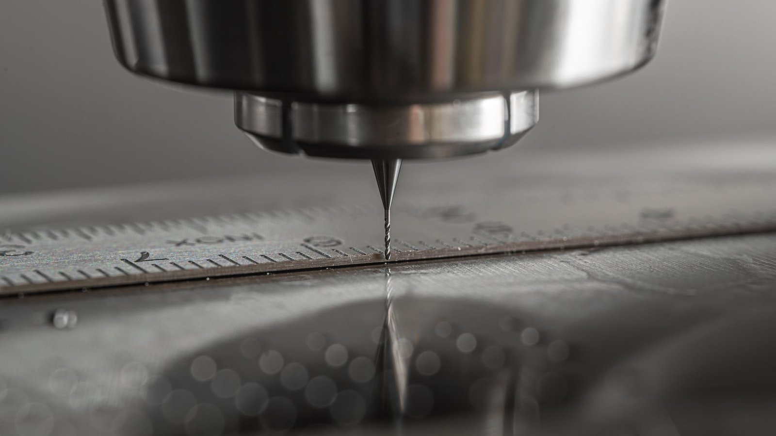
A round tool cannot cut a sharp internal vertical corner. Ever. If you model one, the shop will either quote an EDM operation or simply machine a radius and tell you afterward. Model the radius yourself and you control the fit.
The rule is not merely “radius equals tool radius.” At exactly the tool radius, the cutter is fully engaged in the corner, which spikes tool load and forces a slow feed. Add 20 percent. For a 6 mm end mill with a 3 mm radius, model a 3.5 mm corner. Keep radii consistent too: five different corner radii mean five tool changes, while one repeated radius lets the machine run one tool at full speed. And remember the floor — a flat end mill leaves a small radius where the wall meets the bottom, so do not demand a sharp floor-to-wall junction unless the function requires it.
Hole, Pocket, and Thread Depths the Machine Can Reach
Pocket depth is governed by tool stickout. A cutter extended too far chatters and deflects, so plan on a depth no greater than about four times the corner radius you chose. A pocket with 3.5 mm corners wants to stay under roughly 14 mm deep; go deeper and the shop needs a larger corner radius or a specialty tool.
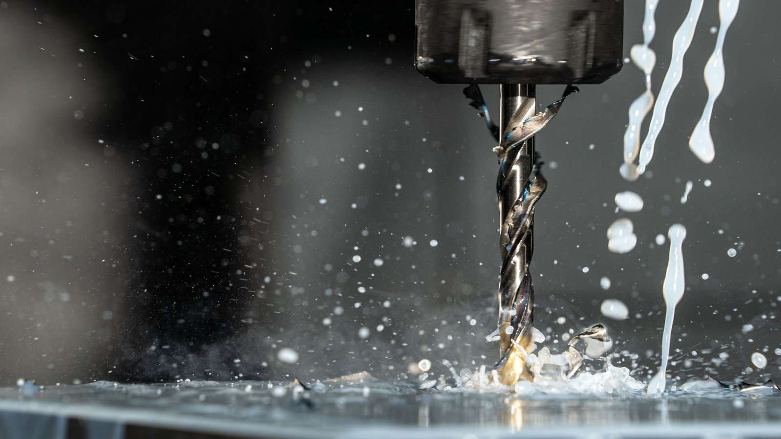
For holes, use standard drill diameters wherever the fit is not critical — a 5 mm hole is free, a 5.13 mm hole needs an interpolated milling pass. Keep drilled depth within four times the diameter for routine work. And model the drill point: a blind hole naturally ends in a 118 to 135 degree cone. If your design genuinely needs a flat bottom, say so on the drawing, because that is a separate operation. For threads, 1.5 times the nominal diameter of engagement carries essentially the full load of the fastener; specifying 3× diameter on an M4 hole adds cost and no strength, a point Protolabs makes in its threaded hole guidelines as well. Leave two or three extra thread pitches of clearance at the bottom of a blind tapped hole so the tap has somewhere to go.
A CNC Machining Tolerances Guide That Protects Your Budget
This is where most first-time quotes go wrong. Applying a tight tolerance to every dimension does not make the part better; it makes it expensive and slow, because each tight callout adds inspection time and often a finishing pass.
A useful hierarchy: a standard shop holds roughly ±0.125 mm (±0.005 in) with no special effort, and ISO 2768-m is a sensible default note. Tightening to ±0.05 mm is a moderate premium. Going to ±0.0125 mm (±0.0005 in) means grinding, temperature-controlled inspection, and a real jump in price. So tolerance only what mates: bearing bores, dowel pin locations, sealing faces, press fits. On a bracket with 30 dimensions, four toleranced callouts is healthy. One detail people forget — anodizing adds roughly 0.005 to 0.025 mm per surface, so subtract it from any tight coated fit.
Design for Manufacturability CNC Checks Before You Export
This is where CNC machining design guidelines become a five-minute habit. Run the list before the STEP file leaves your machine. No sharp internal vertical corners. No undercuts unless you have accepted a turning or EDM operation. Consistent radii, ideally drawn from one or two tool sizes. Wall thickness verified against the ratios above. Text and engraving no finer than about 0.5 mm stroke width and 0.25 mm deep. At least one large flat face available for workholding, plus enough material to clamp. Features grouped onto as few faces as possible. Material named explicitly — 6061-T6 machines beautifully, 7075-T6 is stronger and pricier, and 304 stainless roughly doubles cycle time versus aluminum.
Each is a quick edit in SolidWorks, and each is expensive to fix after a shop has quoted and scheduled the job. If you are still deciding whether the part belongs on a mill at all, our comparison of CNC machining and 3D printing for low-volume parts covers that decision first.
What to Send the Machine Shop Alongside the Model
A clean solid model is necessary but not sufficient. Send a STEP file in AP242 (or AP214) format, since that is the neutral format every CAM system reads without translation errors. Add a 2D drawing carrying only the critical dimensions, the default tolerance note, thread callouts, and surface finish — a drawing with 60 dimensions buries the four that matter. State material and temper, finish (as-machined Ra 3.2 µm is standard), quantity, and which faces are cosmetic.
That package is exactly what we build as part of our SolidWorks modeling service: a parametric model you can revise, a machining-ready STEP export, and a drawing a shop can quote from without asking questions.
Ready to turn your idea into a 3D CAD model? MiniCAD has delivered 7,000+ orders over 9+ years, rated 4.9 out of 5 across 4,470+ Fiverr reviews.
Packages start at $79. Send your sketch, photo or sample through our quote form and get a personal quote within 24 hours. You pay only after you accept it. Questions? Email contact@minicad.io.