You have a part in your hand and no CAD file for it. The supplier went dark, the drawings were lost two decades ago, or the component snapped and nobody sells a replacement. Reverse engineering to CAD is the process of turning that physical object into an accurate, editable 3D model you can modify, print, or send to a machine shop. Done properly it takes measurement discipline, not guesswork — and the difference shows the moment the first replacement part refuses to fit.
What Reverse Engineering to CAD Actually Means
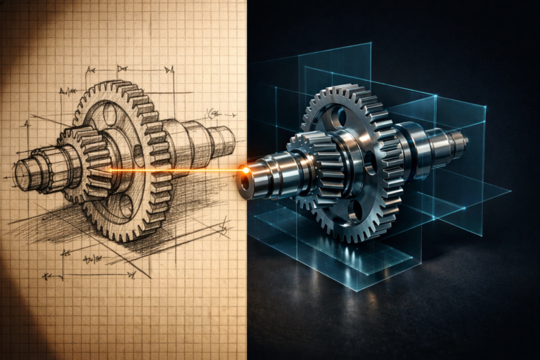
Reverse engineering to CAD is not tracing. Tracing gives you a shape that looks right. Reverse engineering gives you a model built on the original design logic — nominal dimensions, standard hardware sizes, recognizable draft angles and radii — so it behaves correctly when you change it later.
The distinction is commercial, not academic. A traced model measured at 12.03 mm stays 12.03 mm forever. A properly rebuilt model recognizes that as a 12 mm nominal feature with wear and measurement error on top, and models it as 12.00 mm. Scale it, mate it into an assembly, or send it to a CNC shop, and only one of those files behaves. If your starting point is a drawing rather than a physical object, our 2D to 3D CAD conversion workflow covers that route instead.
Choose Your Measurement Method First
Three methods cover almost every job, and choosing wrong wastes a week.
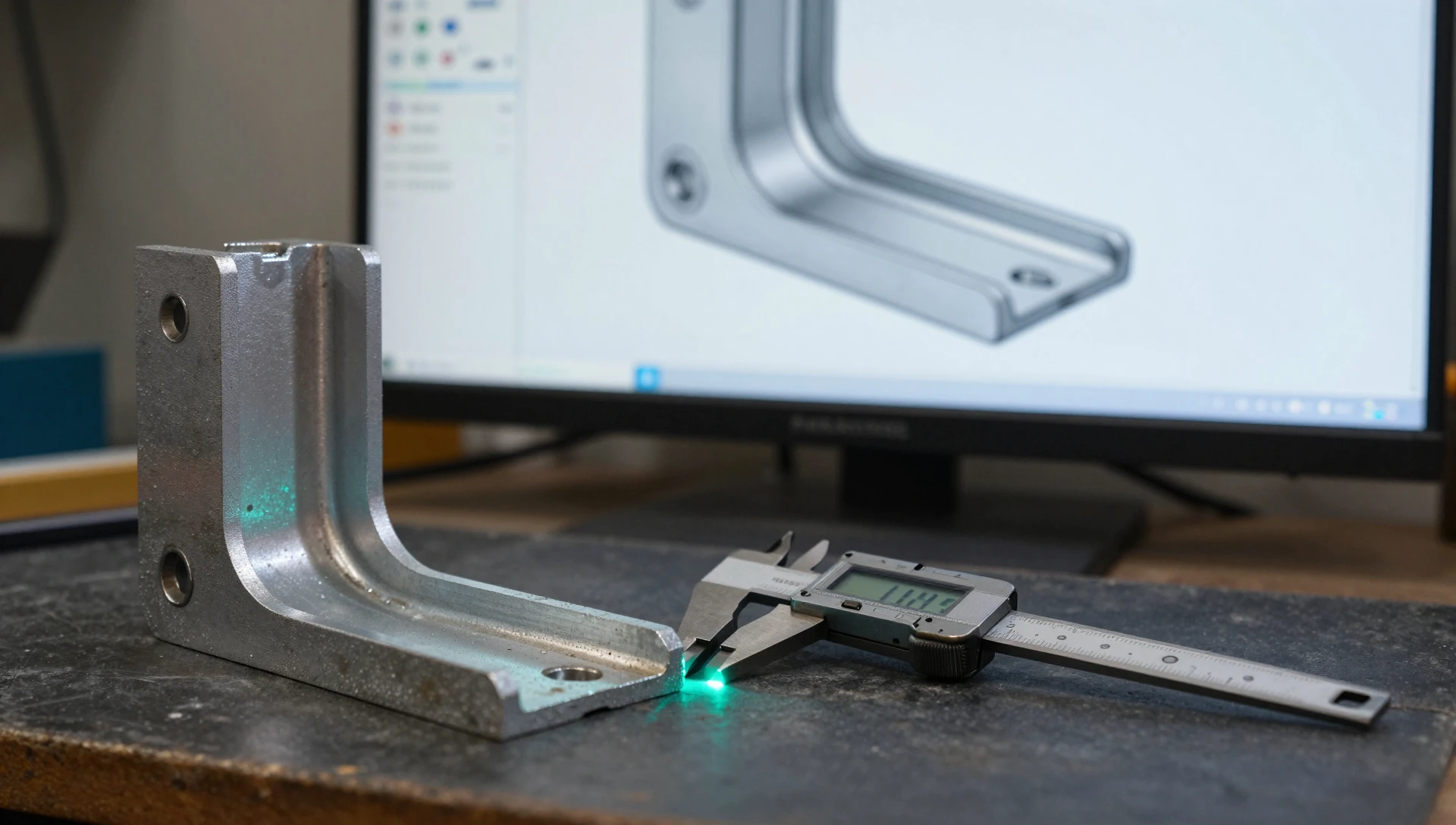
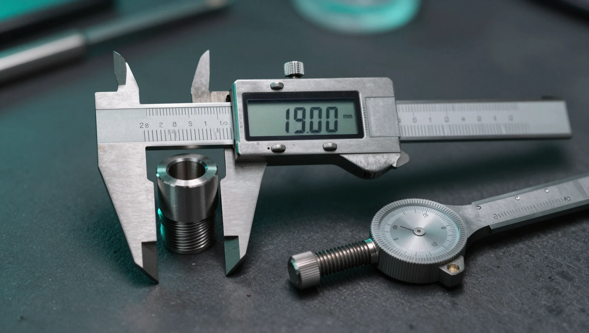
Hand metrology — digital calipers, micrometers, thread pitch gauges, radius gauges, pin gauges. Accurate to roughly ±0.02 mm with a decent caliper. Right for prismatic parts: brackets, housings, flanges, shafts — anything built from planes, cylinders and holes. That covers most mechanical components.
Photogrammetry — dozens of photographs processed into a mesh. Cheap, but accuracy typically lands around ±0.5 mm — fine for overall proportion, useless for anything that has to fit something else.
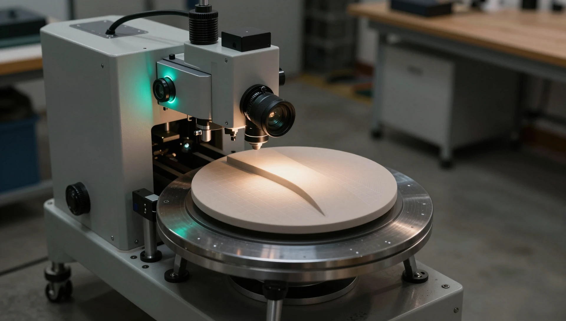
Structured-light scanning — roughly ±0.05 mm on a good desktop unit. Necessary for freeform geometry where no nominal dimension exists: a helmet shell, a turbine blade, an ergonomic grip.
How to Measure a Part for CAD Modeling
Before you measure a part for CAD modeling, establish a datum scheme: one flat face as the primary datum, two mutually perpendicular edges as secondary and tertiary. Every dimension references those three, which stops error accumulating around the part.
Take every measurement three times and record all three. A spread wider than 0.05 mm on a supposedly flat surface tells you the surface is not flat — worth knowing before you model it.
Snap to nominals aggressively. Measured 5.97 mm means a 6 mm shaft. Measured 6.32 mm on an imperial part is a 1/4 inch feature at 6.35 mm. Threads are where most people go wrong: verify pitch with a gauge, because M6×1.0 and 1/4″-20 UNC look nearly identical and are not interchangeable. Cross-reference diameter and pitch against a catalog such as McMaster-Carr before committing a thread callout.
Two traps deserve naming. Molded parts carry draft, typically 1° to 2° per wall — model it in rather than pretending walls are vertical. And injection-molded thermoplastics shrink as they cool, commonly 0.4% to 0.7% for ABS, so the part you hold is smaller than the tool that produced it. If the goal is a new mold, that allowance goes back in.
When 3D Scanning for CAD Earns Its Cost
3D scanning for CAD is genuinely powerful and routinely oversold. It earns its cost on freeform surfaces, on parts with hundreds of features where hand measurement would take days, and on objects too large or fragile to clamp in a vise.
It saves nothing on a simple bracket — scanning, cleaning, aligning and surfacing a mesh often takes longer than twenty minutes with calipers, and the caliper model comes out cleaner. Scanners also struggle with dark, glossy or transparent surfaces without matting spray, and none see inside a blind hole.
Scan to CAD Conversion Without the Mesh Trap
This is where most scan to CAD conversion projects quietly fail. A scan produces a mesh of millions of triangles. Automatic mesh-to-solid tools will convert that into a solid body — technically a solid, practically useless: no feature tree, no editable dimensions, surfaces that wobble by tenths of a millimeter.
The professional route treats the mesh as reference geometry only. Align it to a sensible coordinate system, then create planes through it and sketch real, dimensioned profiles on those planes. You rebuild the part parametrically on top of the scan rather than converting the scan into a part. Reserve automatic surfacing for genuinely freeform regions where no parametric definition exists.
Reverse Engineering in SolidWorks — The Rebuild Sequence
Reverse engineering in SolidWorks works best when the rebuild follows manufacturing order rather than measurement order. Start with the base feature — the extrusion, revolve or casting envelope the original began from. Add primary features next: bosses, pockets, main bores. Then holes, slots, counterbores. Cosmetic detail comes last: fillets, chamfers, ribs, text.
Two habits separate a model that survives revision from one that does not. Drive every dimension you might later change from a global variable or equation, so adjusting one wall thickness updates the part instead of breaking it. And keep fillets at the end of the feature tree, never buried mid-history — a fillet applied early is the most common cause of a rebuild failure later.
Keep sketch relations fully defined. An underdefined sketch in a reverse engineered part is a dimension you have not determined yet, and it will drift the first time someone else opens the file. Our SolidWorks modeling service page lists what each rebuild package includes.

Validating the Model Against the Real Part
Never deliver a rebuilt model without checking it against the object it came from. Pick six to eight checkpoints across the part — overall envelope, critical bore diameters, hole spacing, mating face flatness, thread callouts, wall thickness — and compare CAD against physical measurement. Anything outside ±0.1 mm on a critical fit needs an explanation before it ships.
For parts that mate with something else, print a test article. A single FDM print at full scale costs a few dollars and catches interference that no on-screen inspection reveals. On critical assemblies we print the mating region alone — faster, cheaper, and it isolates the question.
What This Costs and How Long It Takes
A single prismatic part, rebuilt from clear photographs and a measurement list, starts at $34 and turns around in 24 hours. Complex geometry — multi-feature housings, threaded assemblies, parts needing draft and shrink compensation — sits at $69. A full multi-part assembly with drawings runs $174.
You shorten your own timeline with good inputs: photographs of every face against a plain background with a ruler in frame, a written dimension list, a note on material and process, and a statement of which fits are critical. That last item matters more than most people expect — knowing one bore is critical and the rest cosmetic changes how the model gets built. Deliverables should include native SLDPRT, a neutral STEP for machining, STL for printing, and a dimensioned drawing if the part goes to a shop.
MiniCAD has delivered more than 7,000 projects across 40+ countries, holds a 4.9★ rating from 4,470+ verified reviews, and ships most single parts within 24 hours. Send your photographs and measurements and we will tell you whether calipers or a scan is the right route before any work starts. Request a quote or email contact@minicad.io.