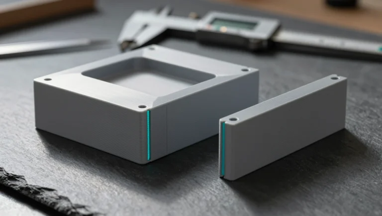
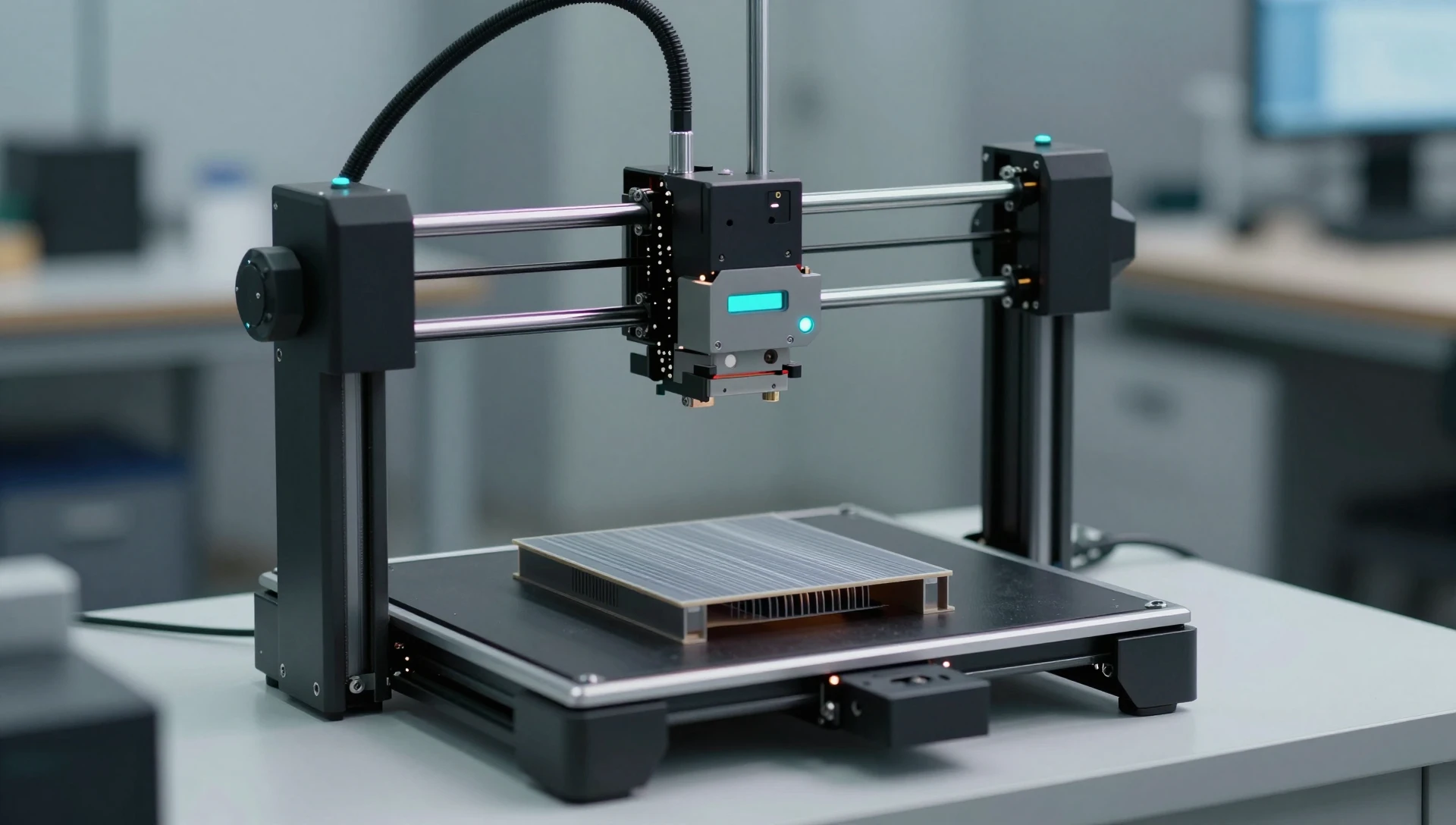
You can spend hours tuning infill density, wall count, and layer height — and still produce an FDM part that cracks on the first real load. In most of those cases the culprit is not a slicer setting but 3D print orientation for strength: the direction the part sits on the build plate relative to its primary load path. FDM is orthotropic — mechanical properties differ sharply depending on which axis you measure — so choosing the wrong build direction can cut tensile strength by 30–50% before a single slicer parameter has been adjusted.
Why 3D Print Orientation for Strength Is the Most Critical FDM Variable
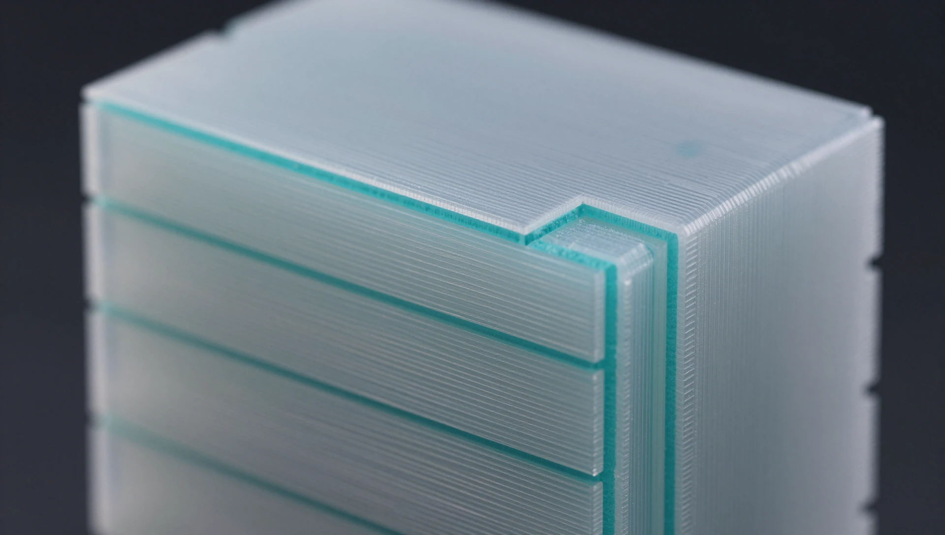
Every FDM layer is a polymer cross-section. Within that layer, extruded beads fuse side by side and form a continuous mass with strength close to the bulk material. Between layers — the Z axis — bonding depends entirely on heat from a freshly deposited bead re-melting the surface below it. That interface is never as strong as the bulk polymer. Published tensile tests on PLA consistently show Z-axis strength 30–50% lower than XY-axis strength at identical infill and wall settings. The gap varies by material, layer height, nozzle temperature, and cooling speed, but the direction of the gap is constant: Z is always the weakest axis.
The practical consequence is direct. If your part’s primary load path — the axis it is pulled, bent, or compressed along in service — runs perpendicular to the layers, you are relying on inter-layer adhesion to carry that load. That bond will fail first.
How Layer Bonding Controls Mechanical Performance
The inter-layer interface contains micro-voids — gaps left when the previous layer cools faster than the incoming bead can fully re-melt it. Slower print speeds, higher nozzle temperatures, and reduced cooling give the bead more time to transfer heat downward and close those voids. Printing PLA at 215–220°C instead of 200°C typically narrows the Z-axis strength gap by around 10–15% without changing geometry or infill. Increasing layer height also helps: a thicker bead deposits more thermal mass on the previous layer, improving inter-layer fusion. But these are corrections at the margin. The best slicer settings cannot overcome a fundamentally misaligned build direction. Orient the part correctly first, then optimize settings.
FDM Build Orientation Rules for Common Part Geometries
The core rule is universal: orient the part so that primary tensile or bending loads run within layers, not across them. Here is how that plays out for specific geometries.
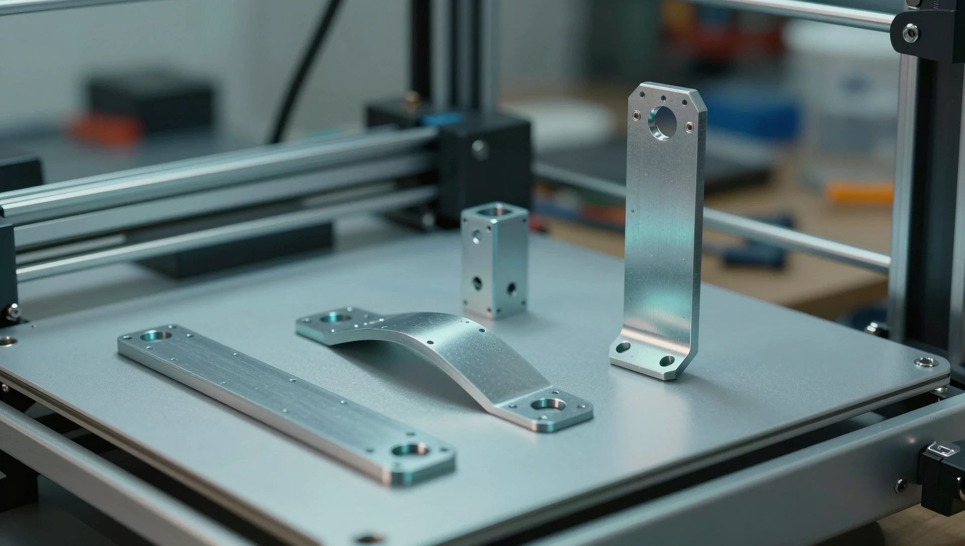
Flat brackets and mounting plates: Always print flat — broad face down on the build plate. This puts the longest dimension and any bending moment in the XY plane where filament continuity is highest. Printing a bracket on its thin edge to eliminate supports will push the bending load into Z and cause layer delamination at the first significant impact or sustained force.
Threaded bosses and bolt holes: Print so threads form in the XY plane. Threads printed vertically — bolt axis parallel to Z — have each thread peak sitting at a layer boundary, the weakest point in the part. If vertical printing is unavoidable, reduce thread pitch to a coarser standard for more contact area and increase perimeters to five or six in that region.
Cylindrical pins and shafts: Print vertically when the primary load is bending around the shaft’s diameter — this maximizes layer continuity around the circumference where bending stress peaks. Print horizontally when axial tension is the primary load, so layers run along the pin’s length and carry tension across the XY plane.
Snap fits and living hinges: Orient so the flexure arm bends in the XY plane. A snap-fit arm printed with the flex direction along Z will crack at the root after one or two deflections — the layer interface cannot sustain repeated tensile cycles. This is one of the most common failures our engineers identify when reviewing client files before a print run begins.
When 3D Printing Layer Orientation Conflicts With Surface Quality
Optimal build direction for strength sometimes creates stair-stepping on curved cosmetic surfaces. A cylindrical boss printed vertically has excellent structural orientation but visible layer lines around its circumference. Printing it on its side smooths those lines but weakens the primary bond direction. In most functional-part scenarios, prioritize structure and plan post-processing for cosmetic surfaces. Sanding from 120 to 400 grit removes stair-stepping on 0.2 mm layer prints in 10–15 minutes, and a light primer coat hides the rest. Only purely decorative, zero-load parts should allow surface quality to override orientation.
Overhangs, Supports, and the Hidden Strength Penalty
Support structures introduce a secondary problem. The interface between a support and the part surface contains a deliberate gap set in the slicer to allow clean removal. That gap means weaker adhesion at exactly the surface the support occupied — and if that surface also carries load, you are compounding the Z-axis weakness with a support-interface penalty. The solution is to design self-supporting geometry: chamfers at 45° or shallower on overhanging faces, fillets at stress-concentration junctions, and split bodies bonded at assembly when a single orientation cannot satisfy all structural requirements. For a deeper look at engineering parts to minimize supports from the CAD stage, this FDM support structures guide covers the design rules in full.
The Best Print Orientation FDM Workflow — From SolidWorks to Slicer
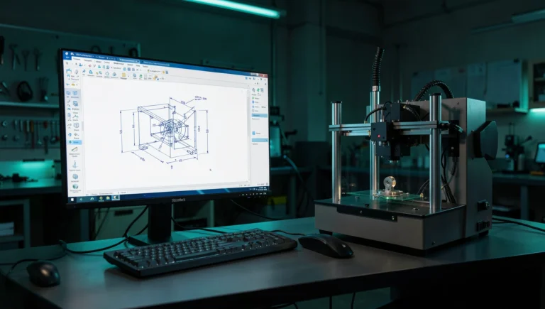
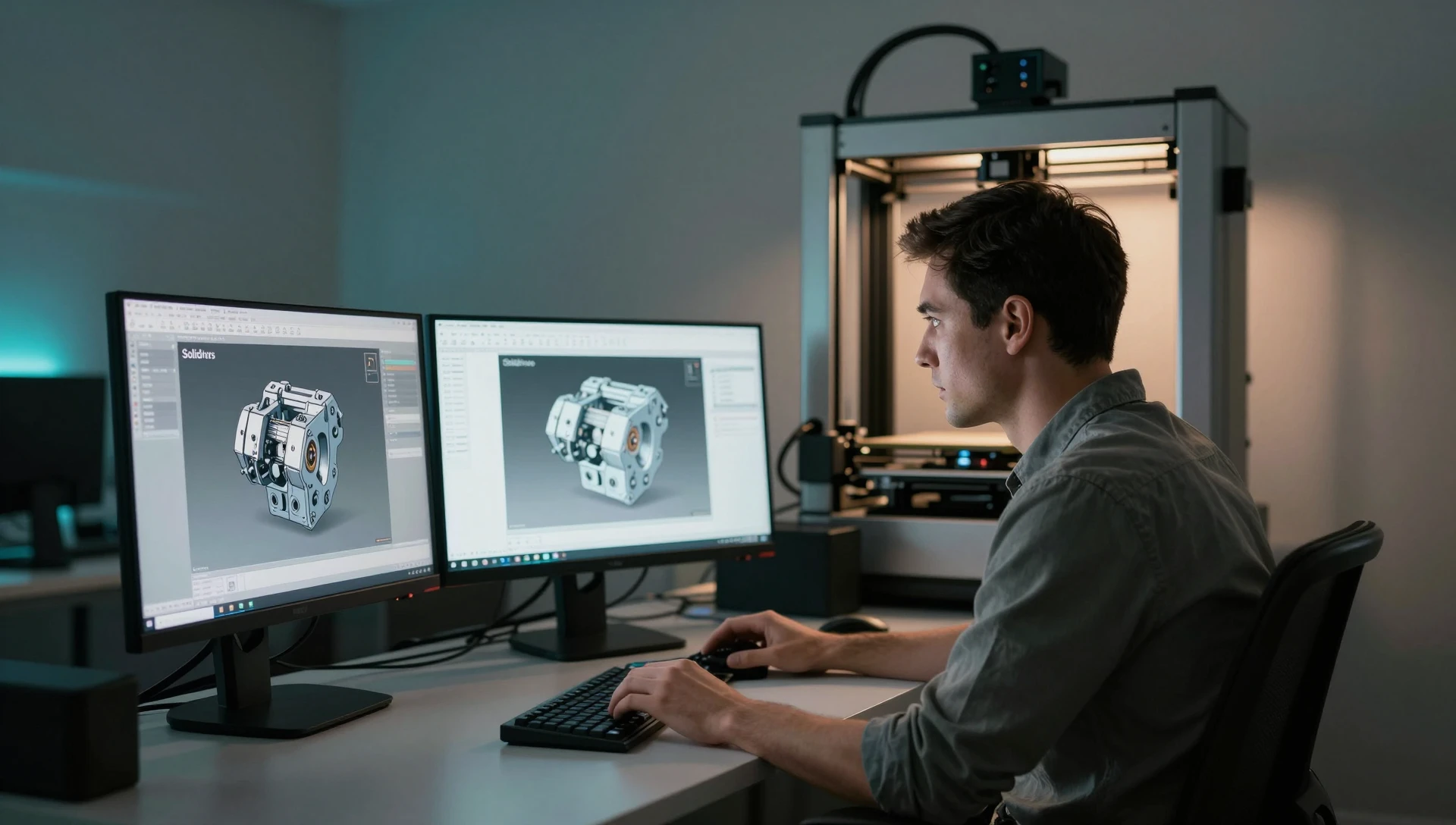
Getting 3D print orientation for strength right means making the key decision at the SolidWorks model stage, not after the STL is open in the slicer. By the time you are rotating a file in PrusaSlicer or Cura, the geometry is committed — adding chamfers or splitting the part means returning to the model. Build these steps into your pre-export workflow:
First, identify the dominant load case: tension, bending, compression, or impact — and mark the load axis. Second, rotate the SolidWorks model so that axis runs in the XY plane. Third, check the resulting overhangs against the 45° self-support rule; add chamfers or fillets to the model where needed. Fourth, verify thread, snap-fit, and hinge orientations against the geometry rules above. Fifth, document the required build orientation in the print brief — this prevents a service provider from reorienting the part for better bed adhesion at the cost of structural alignment.
According to Prusa’s 3D print quality documentation, build orientation is among the highest-impact adjustments a user can make independently of hardware. Most of the performance gain costs nothing — it is a rotation applied before slicing.
Getting a Print-Ready STL File With Orientation Engineered In
A properly prepared print file captures more than geometry. It encodes the intended build orientation, recommended layer height, material choice, and support strategy — so nothing is left to guesswork at the printer. MiniCAD’s engineering team builds these decisions into every print-ready STL file delivered to clients: load paths dictate part orientation from the SolidWorks stage, overhangs are chamfered or split at design time, and the accompanying print brief states the correct face-down orientation explicitly.
Ready to turn your idea into a 3D CAD model? MiniCAD has delivered 7,000+ orders over 9+ years, rated 4.9 out of 5 across 4,470+ Fiverr reviews.
Packages start at $79. Send your sketch, photo or sample through our quote form and get a personal quote within 24 hours. You pay only after you accept it. Questions? Email contact@minicad.io.