Every FDM print leaves the interior mostly empty. What fills that space — and how it fills it — is the infill pattern, and it is one of the most consequential decisions you make before pressing Print. Choose wrong and you get a bracket that cracks under load, a housing that flexes when it should not, or a prototype that burned twice as much filament as the job required. This guide covers every common FDM infill pattern for 3D printing — the geometry behind each option, the density numbers experienced engineers actually use, and the specific settings that match each real-world application type.
What Infill Actually Does Inside an FDM Part
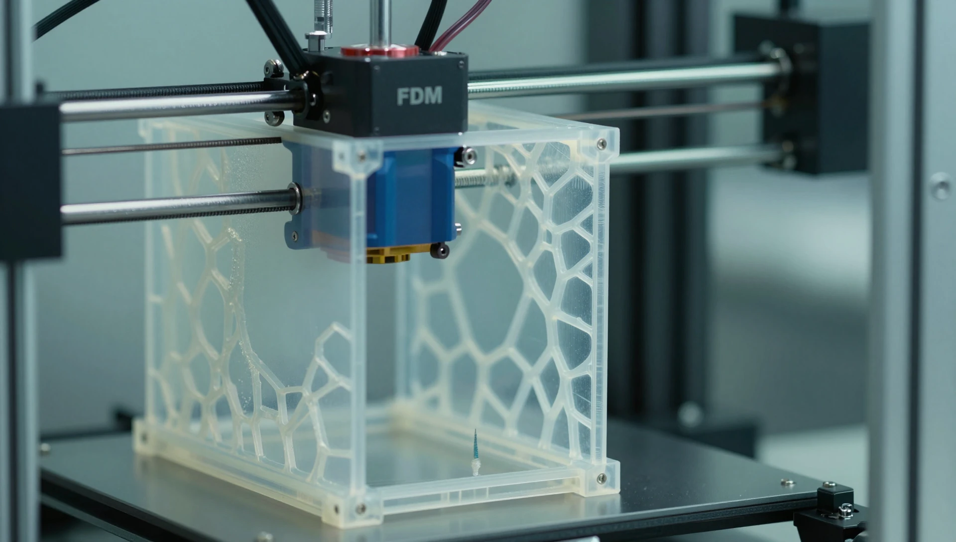
When your slicer generates a toolpath, it creates a solid perimeter shell around the outside of the part — typically 2 to 4 walls — and then fills the interior with a repeating geometric lattice. That lattice is the infill. It supports top surface layers so they do not sag, distributes compressive and tensile loads between the outer walls, and determines how the part behaves under stress.
The two variables you control are the infill pattern (the geometry of the lattice) and the infill density (what percentage of the interior volume is solid). Changing the pattern alone can increase effective strength by 30–40% at the same density, so pattern selection matters as much as the number you dial in. This is the variable that most 3D printing design rules guides treat as a footnote — it deserves more attention than that.
The Most Common FDM Infill Patterns for 3D Printing
Slicers like PrusaSlicer, Cura, and Bambu Studio offer 15 to 20 infill options. In practice, five patterns cover 90% of real-world work.
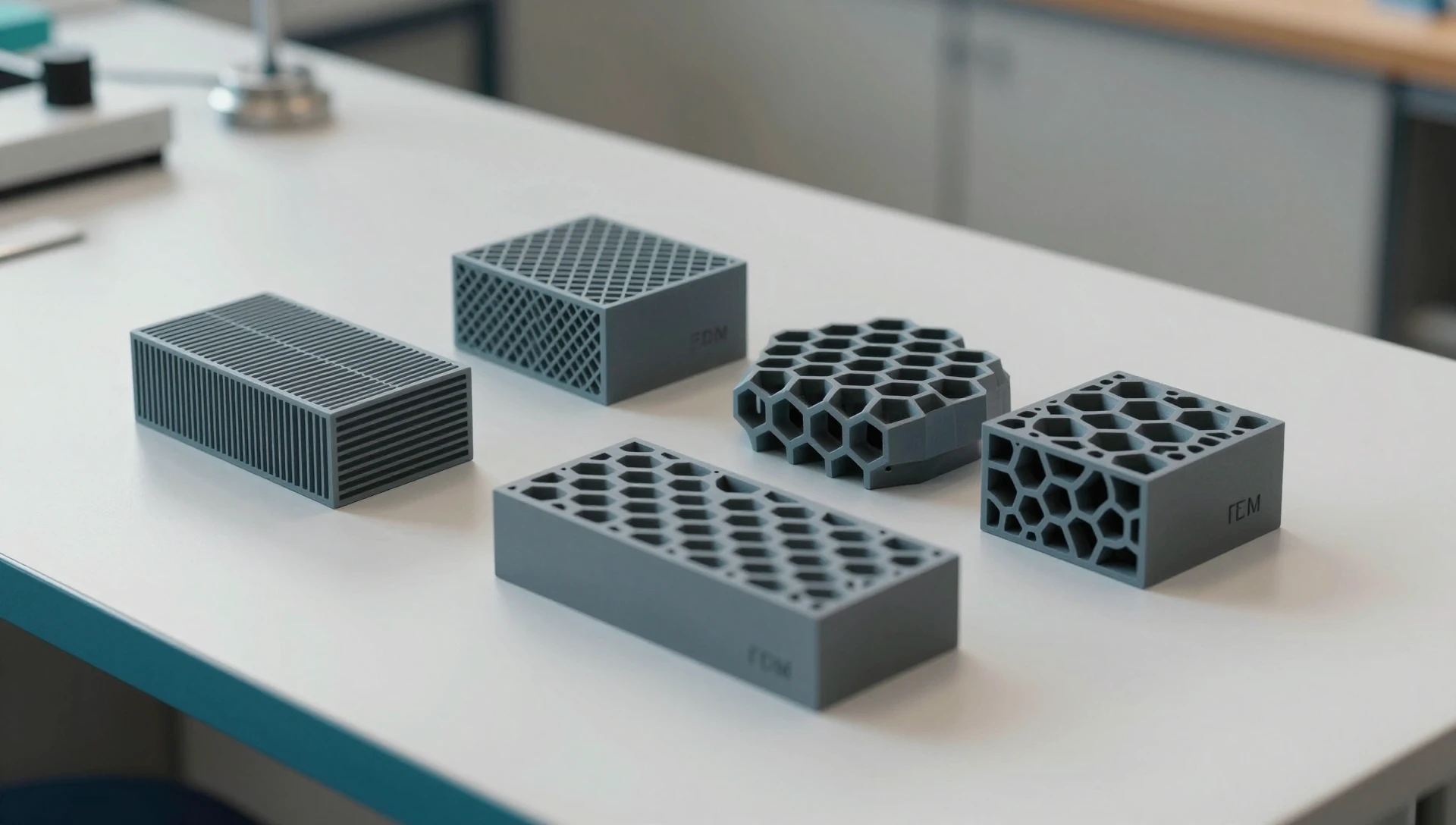
Grid runs extruded lines in two perpendicular directions, forming squares across each layer. It is the default in most slicers, prints fast, and produces consistent top surfaces. Grid handles load along two axes well, but diagonal stress targets the lattice intersections — that is typically where grid-filled parts crack first.
Lines (also called Rectilinear) prints alternating layers of parallel lines, rotated 90° between layers. It uses the least material for a given density and prints fastest of any pattern. Use it for display models and fit-check prints where structural integrity is not the priority.
Triangles introduce a third axis into the lattice, distributing in-plane shear significantly better than Grid. For lightweight structural parts with no impact requirement, triangles at 20–25% density routinely outperform grid at 30%.
Honeycomb (2D) uses regular hexagons — the classic strong-and-light geometry. Hexagonal cells resist compression well and are easy to inspect through thin walls. This pattern suits end-use housings and covers where weight is a concern. The similarly named 3D Honeycomb pattern in PrusaSlicer behaves closer to Cubic; see below.
Gyroid and Cubic Infill — Best Patterns for Load-Bearing Parts
These two patterns represent the current state of the art for functional FDM parts.
Gyroid is a mathematically continuous minimal surface — a 3D wave that curves back on itself with no flat faces. Because the geometry has no preferred orientation, it resists forces equally from every direction — a property engineers call isotropic. Prusa Research’s slicer documentation identifies gyroid as achieving near-equal strength across all three print axes, the only common FDM pattern to do so. A gyroid at 20% density typically matches or exceeds the effective strength of a grid pattern at 35%, and it sheds internal moisture better than flat-lattice options — worth noting for outdoor or food-contact parts. The trade-off: 10–15% longer print times than grid at equal density.
Cubic subdivides the interior into interlocking cubes tilted 45° off each axis, giving excellent compressive strength from multiple directions without gyroid’s print-time cost. Use cubic as the default for functional parts — motor mounts, jigs, enclosure bodies, structural brackets — and step up to gyroid when you need confirmed omnidirectional load performance.
Infill Density: The Specific Numbers Engineers Use
Density is the percentage you type into your slicer. These are the ranges that hold up in production:
5–10%: Visual models, display prototypes, and decorative parts. At 10% gyroid, top-surface support is adequate with minimal material. Avoid grid or lines below 15% — the sparse lattice leaves top surfaces unsupported between walls.
15–20%: General-purpose functional parts with modest loading — housings, covers, non-structural fixtures. This is the sweet spot for balancing material cost and performance on parts that will be handled regularly but not mechanically stressed.
25–35%: Load-bearing brackets, jig bodies, snap-fit clips, and anything that will be drilled or tapped after printing. At 30% gyroid or cubic, a 40 mm span in PLA can sustain 15–25 kg of compressive load before the walls — not the infill — fail.
40%+: High-stress structural parts, press-fit inserts, and thin-walled parts that rely on infill for rigidity. Gains diminish steeply above 50%; an extra perimeter adds more effective strength than raising density from 50% to 70%.
100% solid fill is rarely correct for FDM. It triples print time, increases warping risk in ABS and ASA, and adds negligible strength over 50% plus four perimeters.
How Infill Pattern Affects Print Time and Material Use
The relationship is not linear. Going from 15% to 30% infill on a 100 cm³ part adds approximately 8–12 g of material and 20–35 minutes of print time, depending on the pattern. Gyroid and cubic generate more complex toolpaths than grid or lines; budget 10–15% extra time at equal density.
For parts ordered in quantities of 10 or more, reducing infill from 40% to 20% on non-structural sections typically cuts per-part material cost by 15–20% and cycle time by 25–30%. This is why professional 3D print file preparation should include a pattern and density recommendation, not just a generic default.
Infill Settings for Common Applications
These settings reflect real production usage on PLA and PETG parts.
Display model or product mockup: Lines or Grid, 10–15%. Speed and top-surface quality are the priorities.
Consumer product housing: Cubic, 20–25%. Provides the rigidity needed to prevent panel flex without adding unnecessary weight.
Load-bearing bracket or mount: Gyroid, 30–35%. Equal-direction strength handles the uncertainty of real-world mounting loads. Add a fifth perimeter if wall thickness allows.
Snap-fit clip or living hinge: Gyroid or Triangles, 25–30%. Gyroid’s continuous geometry avoids the stress concentrations at lattice intersections where snap-fits typically fail first.
Jig or work-holding fixture: Cubic, 35–40%. Jigs take sustained clamping and locating force; use a stiff pattern at a density where the infill, not just the perimeters, provides rigidity.
Threaded insert housing: 40–50% with any isotropic pattern, plus a minimum of four perimeters. Heat-set inserts need bulk material to grip — too little infill causes the insert to spin under torque.
When Your CAD Model Has to Be Right Before You Slice
Infill settings cannot fix a bad model. A watertight geometry, correctly sized features, and walls thick enough for the slicer to register as solid perimeters are the foundation that any infill pattern builds on. If the part was modeled with 0.6 mm walls on a 0.4 mm nozzle, the slicer may not generate perimeters at all — and infill has nothing to connect to.
Ready to turn your idea into a 3D CAD model? MiniCAD has delivered 7,000+ orders over 9+ years, rated 4.9 out of 5 across 4,470+ Fiverr reviews.
Packages start at $79. Send your sketch, photo or sample through our quote form and get a personal quote within 24 hours. You pay only after you accept it. Questions? Email contact@minicad.io.