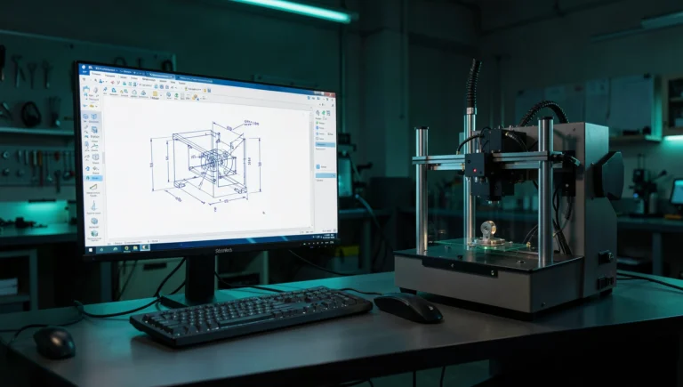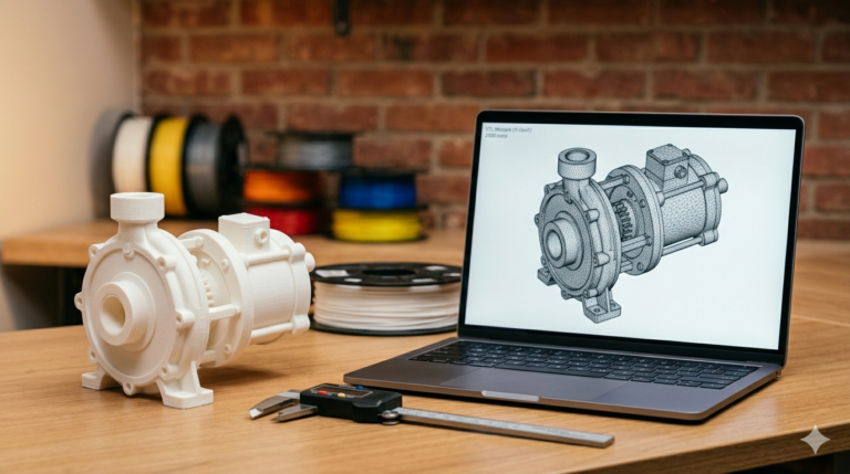
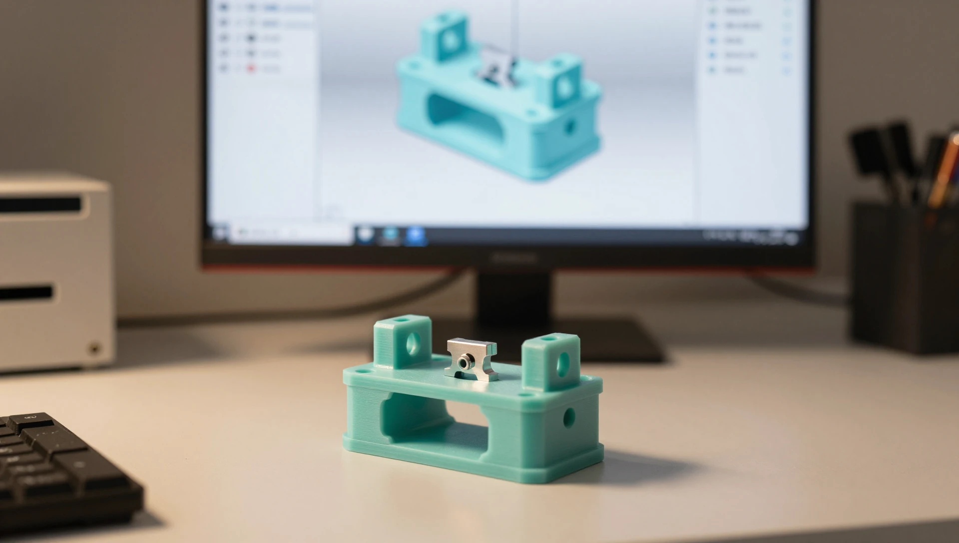
Every engineer who runs a small production line or prototype workshop faces the same calculation: you need a reliable locating fixture to hold a part for drilling, gluing, or inspection, but a machined aluminum jig means a three-day lead time and a $200 minimum. Jig and fixture design for 3D printing breaks that equation. A PETG nest that locates a housing within ±0.3 mm costs $4 in filament and is off the printer in six hours — repeatable through 80–100 assembly cycles before measurable wear appears. This guide covers the material science, tolerance math, and SolidWorks workflow that separate reliable printed tooling from the kind that shifts on the second use.
Jigs vs. Fixtures — Know the Difference Before You Design
A jig guides the cutting tool relative to the workpiece — it moves with the cut. A fixture holds and locates the workpiece in a repeatable position while the tool comes to it. Both can be 3D printed effectively for low-volume runs, assembly aids, inspection gauges, and bench work. Machined steel tooling is the right answer for high-temperature operations, heavy clamping loads (sustained above ~500 N), or production runs exceeding 500 pieces. For everything else, FDM printing offers lead times measured in hours and material costs under $10 per fixture.
Jig and Fixture Design for 3D Printing — Core Principles
Jig and fixture design for 3D printing starts with the same locating logic as traditional tooling but requires adapting several decisions for the process. Apply the 3-2-1 locating principle in CAD before adding any clamping features: three contacts define the primary seating plane, two contacts on a perpendicular face constrain the secondary axis, one contact on the third face stops rotation. A fixture that skips this step requires bench shimming on every setup.
Print orientation: FDM tensile strength parallel to layer lines runs 20–40% lower than perpendicular to them. If the main clamping or locating force will try to split layers, orient the fixture so layer lines run perpendicular to that load. For complex clamps, splitting into two shells — each printed in its strongest orientation and bonded with CA adhesive — consistently outperforms a single-body print in the wrong orientation.
Infill for tooling: Standard display models print at 15–20% infill. Fixtures carrying clamping or impact loads need 40–80% cubic or honeycomb infill. Set this explicitly in your slicer — don’t trust defaults designed for decorative prints.
Material Selection for 3D Printed Tooling
Material choice determines whether your fixture survives its first week in the shop.
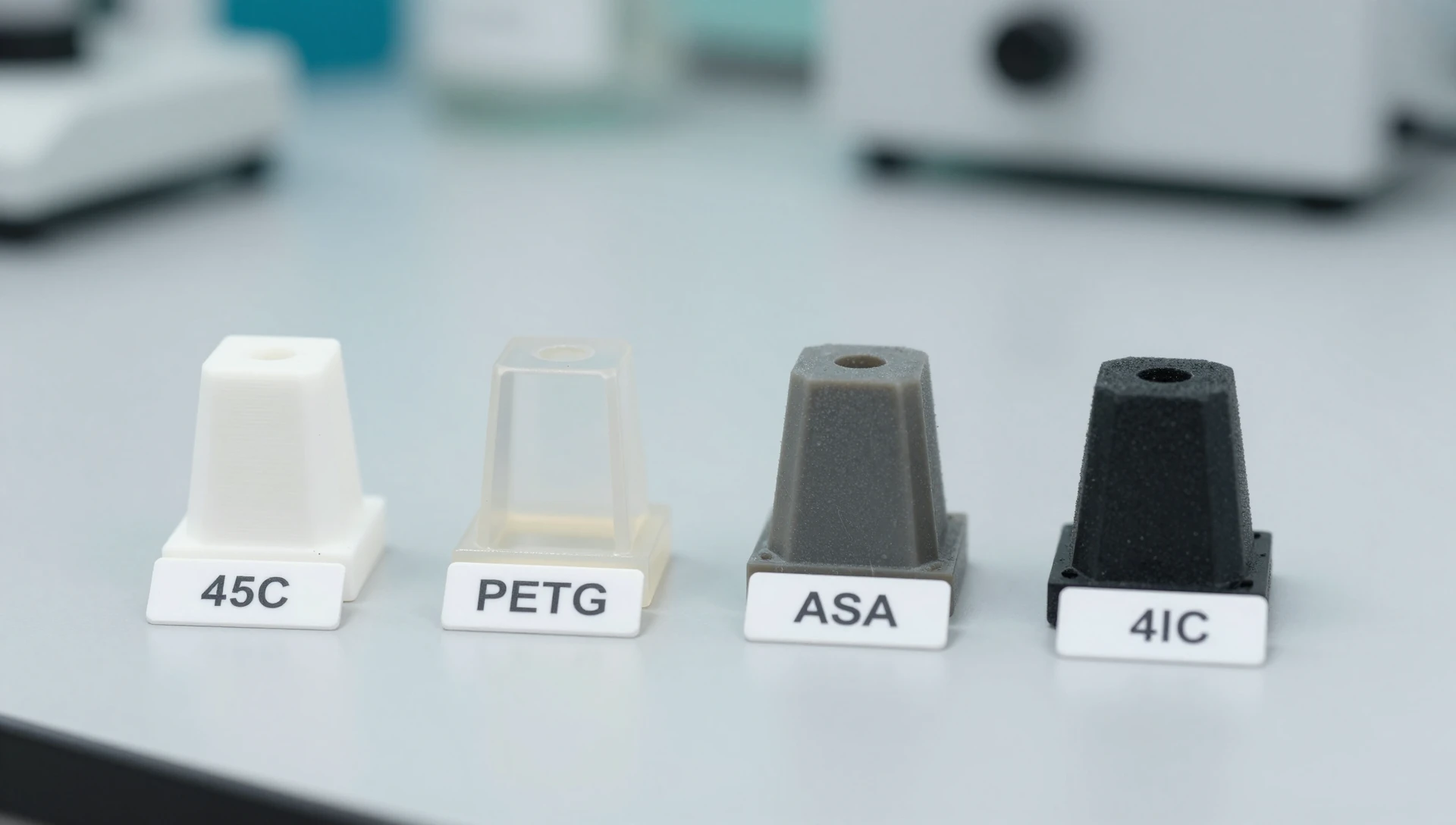
PLA suits locating nests and gauges in climate-controlled spaces. Heat deflection temperature is roughly 60°C — keep PLA tooling away from processes that generate heat or direct sunlight. A PLA locating pin holds position for 50–100 assembly cycles before measurable wear appears, which is acceptable for most prototype runs.
PETG is the shop workhorse. HDT ≈ 80°C, noticeably better impact resistance than PLA, and enough flexibility that locating features snap over bosses instead of fracturing. Default to PETG for fixtures with any mechanical contact.
ASA and PETG-CF are the upgrade for outdoor fixtures or drill jigs that see real thrust loads. Carbon-fiber PETG eliminates most layer-line flex under drill thrust and machines cleanly if you need to seat a metal insert. Cost is roughly 3× standard PETG — worth every cent for functional production tooling.
Nylon (PA12) handles heat, repeated mechanical loading, and chemical splash. HDT exceeds 150°C with excellent fatigue life. Reserve it for critical tooling where failure costs outweigh the harder printing requirements and higher material spend.
SolidWorks Fixture Modeling — The Professional Workflow
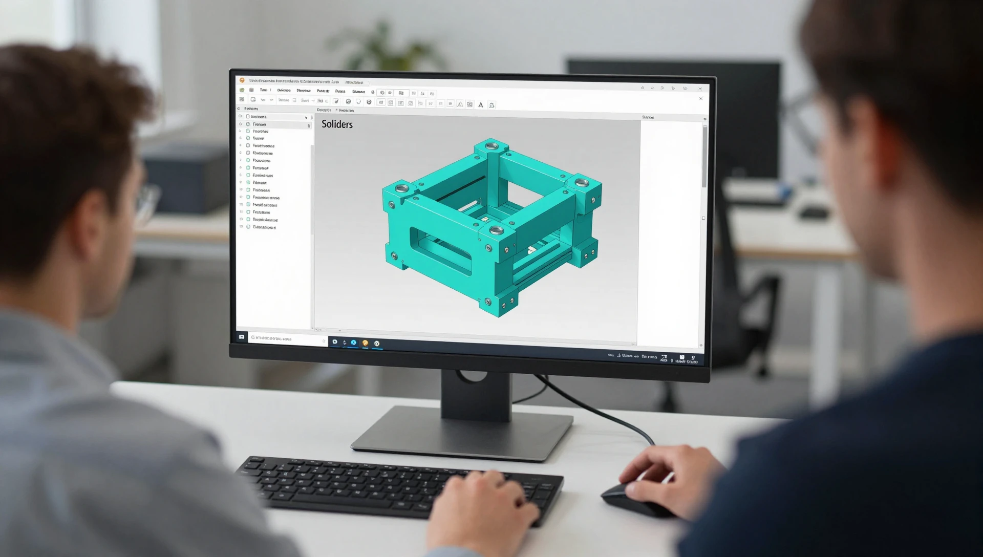
Open a SolidWorks assembly and insert the target part body as a reference component (Insert → Part), then model the fixture around it in context. This links your locating features geometrically to the real part — if a boss diameter changes by 0.5 mm, the nest updates automatically instead of requiring a manual rebuild.
The key features for fixture work: use Offset Surface (inward) on the target part face to generate the nest cavity geometry, then trim to a solid. A 0.15–0.25 mm inward offset gives a firm locating nest in PETG; 0.30–0.40 mm gives a sliding clearance fit in PLA. For drill jigs, place bushing seats with Hole Wizard at nominal drill diameter + 0.05 mm for a light press fit on a standard steel drill bushing — this gives you hardened steel guidance without machining the entire body. Use Mirror Body for symmetric clamps: design one half, mirror it, and create left/right-handed variants by toggling a single suppress feature.
3D Printed Work Holding — What Actually Works
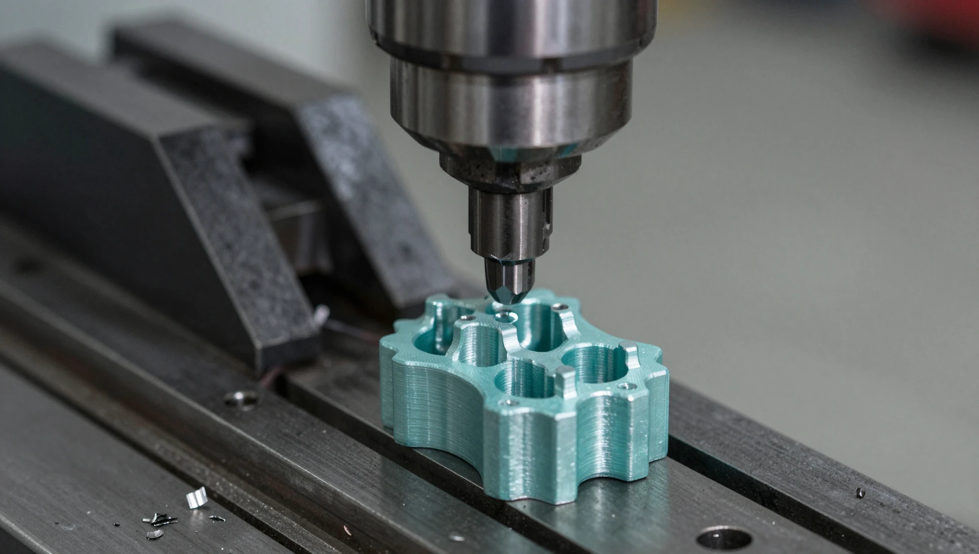
Printed work holding for CNC milling is the most demanding application. Cutting forces are high and positional repeatability must survive tool changes. Three strategies that consistently work in real shops:
Sacrificial fixture with heat-set inserts: Print the body in PETG with M5 insert pockets. Bolt directly to the machine table’s T-slots. The fixture is cheap enough to surface or replace after 20–30 setups — total material and hardware cost under $12 per fixture.
Custom soft jaws: Print PA12 or PETG-CF jaws with a jaw face profile that mirrors the part’s outer geometry, modeled parametrically in SolidWorks. Material cost per jaw set: under $8, versus $60–150 for machined aluminum equivalents from a job shop.
Vacuum fixture for sheet parts: Print a plenum body with vacuum channels and a gasket groove; connect to a shop vac. FDM walls at 0.2 mm layer height and 3 perimeters are airtight enough for light workholding when the channel face is sealed with a thin coat of structural epoxy.
Tolerance Budgeting for Printed Fixtures
A well-calibrated FDM printer holds ±0.1–0.2 mm on features under 50 mm. For locating pins, undersize the radius by 0.2 mm (0.4 mm on diameter) for a sliding clearance fit, or 0.1 mm on radius for a firm push fit. Always print a test pin and measure with calipers before committing to the full fixture body — five minutes of verification saves hours of rework. According to All3DP’s FDM accuracy testing, even budget desktop printers can hold ±0.1–0.2 mm on small features when properly calibrated, making them viable for precision locating work.
Watch tolerance stacking in fixtures with multiple locating features. Three pins each with ±0.15 mm positional error produce a worst-case stack of 0.45 mm — acceptable for a gluing nest, not for an inspection gauge checking a ±0.2 mm feature. For precision gauges, print undersized and hand-ream or drill the critical bore to final dimension using a calibrated drill press.
When to Use a Custom Jig Design Service
A simple locating nest takes an experienced SolidWorks modeler about an hour. A multi-part clamping fixture with in-context references, hardware seats, split-body print optimization, and assembly documentation takes a full day or more. If your team lacks SolidWorks experience, engaging a custom jig design service is faster and cheaper than learning parametric CAD from scratch for a one-off tooling project — especially when the fixture directly supports production throughput.
MiniCAD has modeled production fixtures for machine shops, electronics assemblers, and product manufacturers across 40+ countries — always in SolidWorks, always delivered as print-ready STEP and STL files. Our 7,000+ completed projects carry a 4.9★ rating with 4,470+ verified reviews, and most fixture CAD work turns around in 24 hours. Explore our SolidWorks modeling service or request a free quote — describe your workholding challenge and we will send a scoped proposal the same day. Reach us at contact@minicad.io.