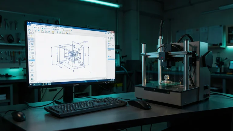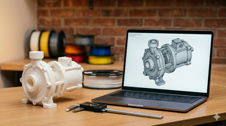
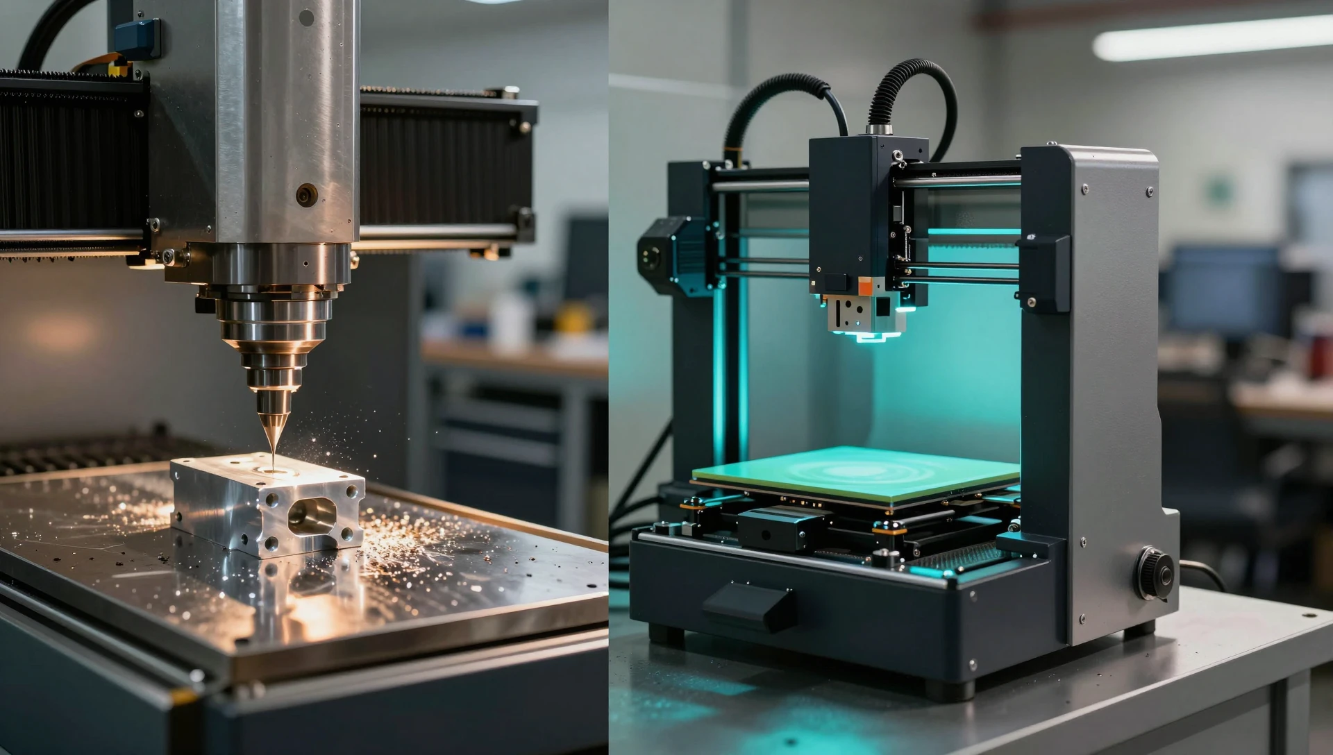
Choosing between CNC machining and 3D printing for a run of 5 to 100 parts is one of the most consequential decisions a product developer makes. The debate over cnc vs 3d printing for low-volume parts rarely has a single correct answer. It hinges on four variables: the material your part genuinely requires, the dimensional tolerance it must hold, how many units you need per run, and whether the geometry is even machinable with conventional tooling. Get the choice wrong and you end up reworking fixturing mid-run or discovering that a printed part creeps under load. Get it right and you have a production path that scales.
What Drives the CNC vs 3D Printing Decision
Most comparisons frame this as a cost question: CNC is expensive for small runs, so 3D printing wins. That framing is correct but incomplete. The real governing factors are material requirement, tolerance class, quantity, and part geometry — in roughly that order. Cost is an output of those four inputs, not a standalone driver.
If your part must be metal — for thermal conductivity, structural load, or regulatory compliance — CNC is your default. Metal additive processes (DMLS, SLM) bring post-processing requirements that typically exceed CNC cost below 100 units. If an engineering polymer suffices, additive becomes genuinely competitive on both cost and lead time. Tolerance draws the second boundary: ±0.05 mm or tighter on a critical feature typically rules out FDM and narrows SLA material choices significantly.
When CNC vs 3D Printing for Low-Volume Parts Favors Additive
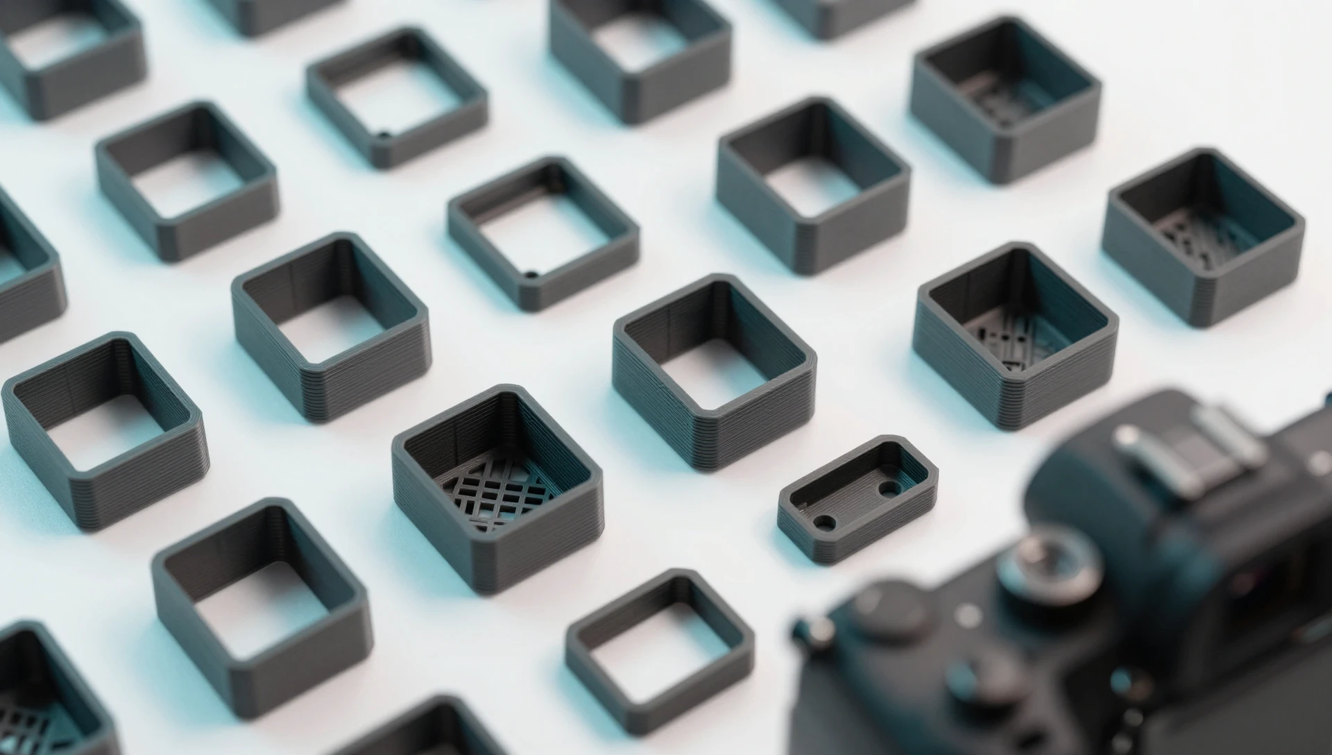
3D printing wins most clearly on geometry complexity. Internal channels, lattice infill, compound undercuts that require multiple setups and custom fixtures in a mill — these are economically impossible at low quantities in CNC. A PA12 nylon MJF part or an ASA FDM build incorporates all of these features in a single run with zero setup cost.
Speed of iteration is the other structural advantage. A revised SolidWorks model goes to a physical part in hours — no toolpath reprogramming, no new fixtures, no minimum order tied to setup amortization. For a part that is still being validated, every cycle eliminated is days off your timeline and hundreds of dollars saved in sunk tooling.
For quantities under 25 units, FDM in PETG, ASA, or Nylon 12 routinely matches machined nylon for brackets, housings, and non-load-bearing structural components. MJF in PA12 produces isotropic parts that hold up in real assemblies. Our prototype design service prepares and validates the SolidWorks geometry for whichever additive process your quantity and material require.
When CNC Machining vs 3D Printing Favors the Mill
The calculation changes when material is non-negotiable. Aluminum 6061, 316L stainless, brass, titanium — CNC handles all of them with precision and repeatability. Metal 3D printing exists, but per-part costs and post-processing (HIP, heat treatment, surface grinding) are rarely justified below 100 units unless the geometry is truly unmachineable.
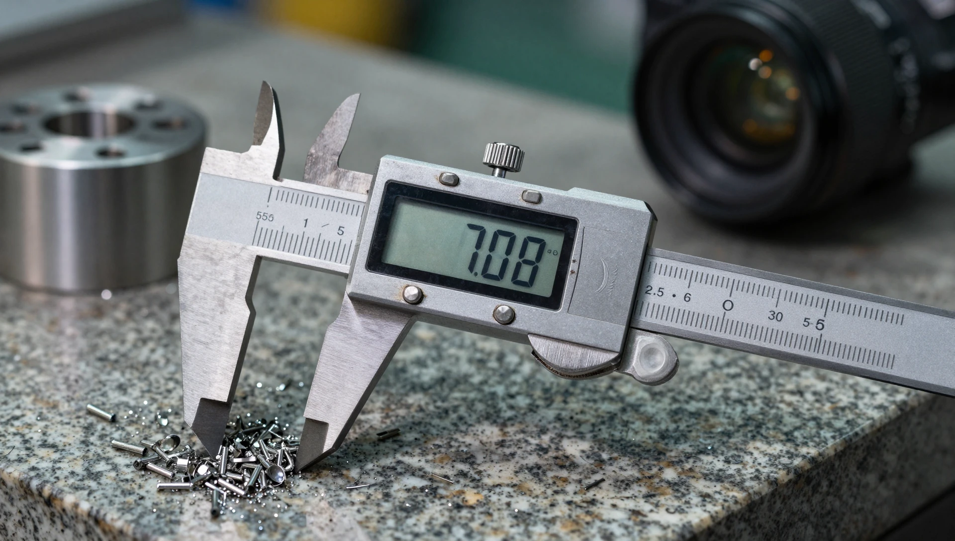
Tolerance is the second driver. Machined parts routinely hold ±0.025 mm (±0.001 in) on critical dimensions — the class of fit a bearing bore, O-ring groove, or press-fit insert demands. The best industrial FDM delivers ±0.2 mm; SLA tightens to roughly ±0.05 mm in select resins. Standard CNC machining tolerance classes are backed by decades of tooling and metrology. When tolerance is the governing constraint, that heritage matters.
Sustained loading is the third factor. FDM parts can delaminate along layer lines under cyclic stress. Bar stock and billet have no layer boundary — the part is fully isotropic. For fatigue-loaded components, machinable metals and Delrin (POM) or PEEK outperform printed alternatives in every structural property. Knowing when to use cnc over 3d printing often comes down to one question: will this part fail differently with layer lines? If yes, machine it.
Material Reality: What Each Process Can Handle
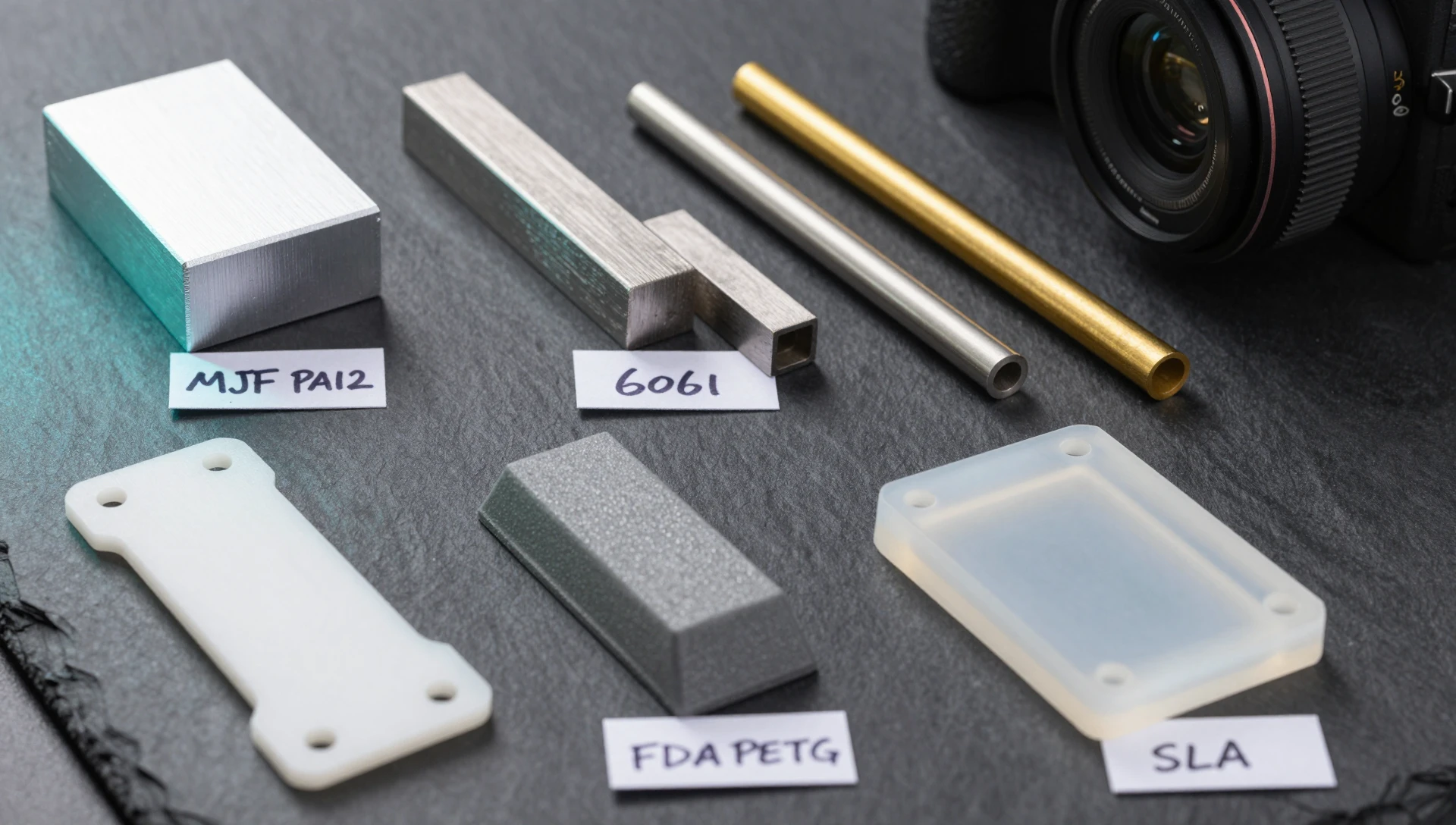
FDM covers PLA, PETG, ABS, ASA, Nylon, TPU, and carbon-fiber-filled composites. SLA covers ABS-like and engineering-grade resins. MJF covers PA11, PA12, and glass-filled PA12 — the closest additive family to machined nylon in isotropic mechanical performance. CNC spans aluminum, steel, stainless, brass, copper, titanium, Delrin (POM), PEEK, and UHMWPE. Delrin machines cleanly into precision gears and sliding bushings that PA12 cannot replicate under continuous load.
Match the process to the material the part actually requires. Never choose a manufacturing process first and then rationalize the material around it.
Tolerances and Surface Finish: The Numbers That Matter
FDM parts arrive with visible layer lines at 0.1–0.2 mm height. SLA has fine surface texture. MJF output has a chalky, granular finish that needs tumbling or bead blasting for cosmetic applications. Post-processing adds 1–3 days and real cost to reach a finished standard. Machined parts come off the mill with a consistent surface that needs minimal finishing for most functional uses.
For consumer housings where surface quality is a selling point, CNC wins unless you budget for printed post-processing. For internal components no end-user ever sees, the finish difference is irrelevant. Map visible requirements to the process, not a generic quality assumption — a machined housing costs more per unit; a post-processed printed housing costs more in labor and time.
3D Printing for Low-Volume Manufacturing — The Clearest Win
The strongest argument for 3d printing for low volume manufacturing is on-demand inventory with zero tooling amortization. Order 10 units this month and 20 next at the same unit price. The file sits on a drive and produces parts on demand. For a startup with uncertain launch volumes, this eliminates the risk of 500 machined units becoming scrap after a single design revision.
Custom configurations strengthen the case. Additive treats every variant identically — each size or mounting pattern runs from the same process. CNC requires new toolpaths and often new fixtures per configuration. A well-prepared set of STL files covering all variants typically beats CNC on total program cost from the very first production run.
A Practical Framework for Small Batch Manufacturing Methods
Work through four questions before committing to either process.
Step 1 — Material: Must the part be metal under real load, or does polymer suffice? If metal, start with CNC. If polymer, continue to Step 2.
Step 2 — Tolerance: Tightest critical dimension? Below ±0.1 mm: CNC. Between ±0.1 and ±0.2 mm: SLA or precision FDM. Above ±0.2 mm: standard FDM or MJF without secondary operations.
Step 3 — Quantity: Under 25 units: additive wins on total cost in almost every case. 25–100 units: get quotes from both and compare delivered cost including post-processing. Above 100 units: CNC often reaches cost parity and wins on cycle time and process consistency.
Step 4 — Geometry: Can a mill reach every critical feature without custom fixturing? If yes, CNC is fully viable. Internal channels, compound undercuts, or topology-optimized structures push the decision toward additive.
When all four answers are clear, the decision usually makes itself. If it still does not, prototype both. The cost of two small test runs is almost always less than a wrong production commitment discovered mid-launch.
MiniCAD has modeled production-ready geometry for both manufacturing paths across 7,000+ projects in 40+ countries — earning a 4.9★ rating from 4,470+ verified clients. Whether you need print-ready STL files for an additive run or precise STEP geometry for a machinist, we deliver in 24 hours. Submit your project brief and we will have your files ready today. Questions? Reach us at contact@minicad.io.