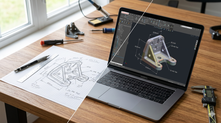

Your model is finished, the STEP file is exported, and the machine shop still emails five questions before it will quote. That gap is exactly what a SolidWorks manufacturing drawing closes. A 3D file describes shape; a drawing describes intent — which surfaces matter, how far each one is allowed to move, what the part is made of, and how it gets inspected. Skip the drawing and you hand the shop permission to guess. You then pay for that guess twice: once in the first batch, once in the rework.
Why a SolidWorks Manufacturing Drawing Still Earns Its Keep
A neutral 3D file carries geometry and nothing else. It does not carry tolerance, material, surface finish, thread class, or a revision number. Cosmetic threads modeled in SolidWorks export as plain cylinders — the shop sees a hole, not an M6 tap.
We rebuilt an aluminum bearing housing last year for a client who had sent only a STEP file. The bore was modeled at a nominal 12.000 mm. The shop machined it to its default ±0.125 mm, landed at 12.09 mm, and the bearing spun in the bore. One line on a drawing — ⌀12 H7 — would have made that bore correct on the first run. The drawing is also the document a quality department measures against and the one a purchase order references. Without it there is no agreed definition of a good part.
SolidWorks Drawing Template Setup That Prevents Rework
Most drawing problems trace back to a template nobody configured. A proper SolidWorks drawing template setup takes an afternoon and then pays out on every job.
Build two files, not one: a sheet format (.slddrt) holding the border and title block, and a template (.drwdot) holding the document settings. In Document Properties set the standard to ISO or ASME, projection to first or third angle to match your region, units to millimeters at two decimal places, and annotation font to 3.5 mm. Link every title block field to a custom property — part number, material, finish, revision, designer, date — using the $PRP syntax so the fields populate straight from the part file. Save both to a shared folder registered under System Options, File Locations. After that, a drawing that reads correctly is the default rather than an act of discipline.
Choose Views for Clarity, Not Coverage
Machinists read a drawing in the orientation they will clamp the part. Set the front view to the primary machining setup, then add only the projected views that reveal something new — three orthographic views cover the majority of prismatic parts.
Use a section view for anything internal: counterbores, blind pockets, sealed cavities. Use a detail view at 2:1 or 5:1 for small features such as O-ring grooves or 0.5 mm chamfers that are unreadable at sheet scale. Add one shaded isometric in a corner for orientation, and never dimension it. If a view carries no dimension and clarifies nothing, delete it. A crowded sheet costs quoting time, and quoting time gets priced into your part.
Dimensioning Best Practices for CNC Parts
The dimensioning best practices for CNC parts that matter most concern where dimensions originate. Chain dimensioning stacks error: three features chained at ±0.1 mm each put the last feature ±0.3 mm from the first. Dimension from a single datum face instead — baseline or ordinate — and every feature inherits the same ±0.1 mm from a common origin.
Reference the faces the shop actually touches in the setup, not arbitrary construction geometry. Use the Hole Callout tool so a tapped hole reads M6x1 – 6H ▼ 12 rather than a bare diameter, and specify depth as full thread depth, not drill depth. Dimension each feature exactly once; a duplicated dimension is an invitation to a discrepancy. Never dimension to the tangent point of a fillet — that point moves as the radius changes.
Engineering Drawing Tolerance Callouts That Shops Respect
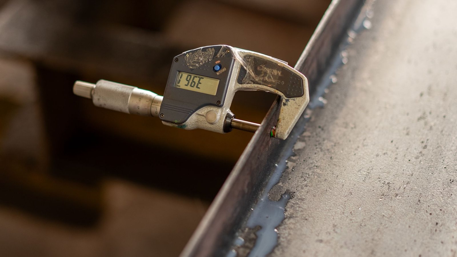
Engineering drawing tolerance callouts are where budgets are won or lost. Put a general tolerance block in the title block — ISO 2768-m, or a flat ±0.13 mm — then tighten only the features that actually function. Standard 3-axis milling holds about ±0.125 mm without effort. Asking for ±0.05 mm adds a modest premium. Asking for ±0.025 mm pulls in grinding, temperature-controlled inspection, and a 30–60% price adder on the whole part.
Use geometric callouts where they genuinely help. A bolt pattern toleranced as position ⌀0.2 at MMC gives the shop more usable material than ±0.1 in X and Y, and costs less to hold. Define datum A as the primary mounting face, B and C as the locating edges, and apply flatness or perpendicularity only to surfaces that mate. Surface finish follows the same logic: as-machined Ra 3.2 µm is free, Ra 1.6 µm needs a finishing pass, and Ra 0.8 µm needs grinding or lapping — the roughness ranges by process published by Engineering ToolBox show exactly where each method tops out.
What a Machine Shop Needs on a Drawing Beyond Geometry
Ask ten shops what a machine shop needs on a drawing and the answers converge on the notes block, not the dimensions. Specify the alloy and temper — 6061-T6, not “aluminum” — because 6061 and 7075 machine and anodize differently. State the finish completely: “Anodize Type II, black, per MIL-A-8625” leaves nothing to interpretation.
Add a deburr note: “Break all sharp edges 0.2–0.4 mm unless otherwise specified.” Call out hardware separately — heat-set inserts, dowel pins, helicoils — with part numbers, and say whether the shop installs them. Include quantity, because a run of 5 is programmed differently from a run of 500. Flag the two or three critical dimensions you want reported on a first-article inspection, and add “Do not scale drawing.” If preparing this package is not how you want to spend your week, our technical drawing service produces shop-ready sheets from an existing model.

Export the Package and Control the Revision
A finished SolidWorks manufacturing drawing ships as a package, not a single file. Send humans a PDF and machines a solid model. The PDF carries the drawing; the STEP AP214 file carries the geometry the CAM programmer imports; a DXF carries any flat pattern for laser cutting. Our comparison of STL versus STEP files explains why mesh formats have no place in a machining package.
Then control the revision. Keep a revision table on sheet 1 with letter, description, and date, and change the letter whenever a dimension moves — even by 0.1 mm. Name files so the revision is visible before anyone opens them: PN-1024_REV-B.pdf. Zip the PDF and the STEP together and send one archive. Shops quoting from an outdated sheet is the single most common cause of a scrapped batch, and it costs nothing to prevent.
Ready to turn your idea into a 3D CAD model? MiniCAD has delivered 7,000+ orders over 9+ years, rated 4.9 out of 5 across 4,470+ Fiverr reviews.
Packages start at $79. Send your sketch, photo or sample through our quote form and get a personal quote within 24 hours. You pay only after you accept it. Questions? Email contact@minicad.io.