You printed the enclosure, drove a screw into the plastic boss, and it held — until the third time you opened it. Then the boss cracked or the thread stripped, and the part became scrap. Threaded inserts for 3D printed parts solve this permanently, and they cost about eight cents each. The problem is that most models we receive are not designed for them: the holes are the wrong diameter, the bosses are too thin, and the insert either falls straight through or splits the wall on the way in.
Why Plastic Threads Fail Under Real Loads
An FDM part is a stack of bonded layers. A thread cut or printed into that stack transfers load across those layer bonds, which are the weakest direction in the part — typically 40 to 60 percent of the strength you get along the layer.
In our shop testing, a machine screw driven directly into a 3.0 mm printed hole in PLA holds roughly 100 to 150 N of pull-out before the thread shears, and two or three removals kill the engagement. A brass heat-set insert in the same boss holds 300 to 500 N and survives hundreds of cycles, because the load goes into a knurled metal body locked into remelted plastic on all sides.
Threaded Inserts for 3D Printed Parts Versus the Alternatives
Four realistic options, each with a correct use case.
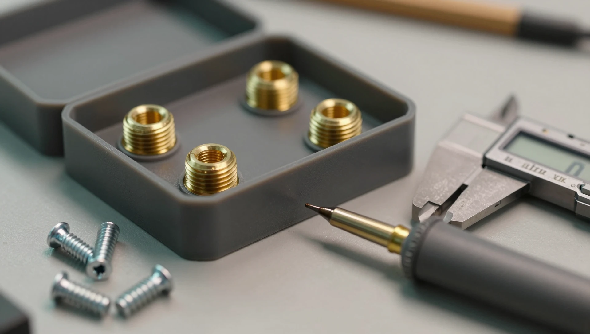
- Heat-set brass inserts — best for anything opened more than once: enclosures, battery doors, lids, fixtures. About $0.05 to $0.15 per insert in packs of 100, plus a soldering iron and tips at $25 to $40 once. McMaster-Carr lists the standard heat-set geometries.
- Thread-forming screws for plastics — a wide, shallow profile that forms its own thread in the boss. Cheap at volume for single-assembly parts, but grip fades after a few cycles.
- Captive hex nuts — a pocket that traps a standard nut. No hardware cost and very strong, but it needs a side-entry slot or a paused print, and a loose pocket lets the nut spin.
- Printed threads — only at M6 and above, and only for low-cycle, low-torque cases such as a lens cap. Model the real helix and add 0.2 mm clearance on the major diameter.
Heat Set Inserts 3D Printing — Sizing the Hole Correctly
This is where most models go wrong. The hole is not clearance for the insert; it is an interference fit that the heat resolves. Model the hole at the insert’s nominal outside diameter, not larger. Your printer already comes in 0.1 to 0.2 mm undersize on a vertical hole at that scale, and that undersize is the interference you want.
Working numbers for the common metric brass inserts, measured against parts we ship:
- M2 — insert Ø3.2 mm × 4.0 mm long → hole Ø3.2 mm, depth 4.6 mm
- M2.5 — insert Ø3.5 mm × 5.7 mm → hole Ø3.5 mm, depth 6.3 mm
- M3 — insert Ø4.0 mm × 5.7 mm → hole Ø4.0 mm, depth 6.3 mm
- M4 — insert Ø5.6 mm × 8.1 mm → hole Ø5.6 mm, depth 8.7 mm
- M5 — insert Ø6.4 mm × 9.5 mm → hole Ø6.4 mm, depth 10.1 mm
Always add 0.5 to 0.6 mm of depth below the insert. Displaced plastic has to go somewhere, and a blind hole with no relief pushes the insert back out as it cools. Add a 0.5 mm chamfer at the mouth so the insert self-centres. If your printer is not calibrated, print a test block with all five diameters first — the same discipline covered in our guide to tolerances and clearances for 3D printing.

Screw Boss Design for 3D Printed Parts
A correctly sized hole in an undersized boss still cracks. We design to a minimum of 2.0 mm of solid material around the insert in every direction. For an M3 insert at Ø4.0 mm, that means a boss outside diameter of at least 8.0 mm. Below that, the melt front reaches the outer wall and the boss bulges or splits.
Three details matter as much as wall thickness. Set perimeters to 4 or more so the boss is solid shell rather than infill — infill under an insert collapses. Add a 1 mm fillet where the boss meets the floor or side wall, because a sharp internal corner is a crack initiator. And never place a boss on a thin unsupported floor: tie it to a wall with a rib, or thicken the local floor to 2.5 mm.
For enclosures, the boss and the lid clearance hole are designed together — the clearance hole gets +0.3 mm over the screw major diameter so tolerance stack does not fight you at assembly. The wider geometry is covered in our 3D printed case design guide.
How to Add Threads to 3D Printed Parts on the Bench
Installation takes 30 seconds once the geometry is right. Set the soldering iron to roughly 200 to 220 °C for PLA, 230 to 250 °C for PETG and ABS. Too hot and the plastic goes runny and the insert sinks crooked; too cold and you push instead of melt, and the boss splits.
Seat the insert on the tip, start it square in the chamfer, and let its own weight plus light pressure carry it down over five to eight seconds. Stop when the flange is 0.1 mm proud, then press it flush with a flat metal surface — this leaves a clean face and pushes displaced plastic back around the knurls. Let it cool 30 seconds before applying load. If it goes in crooked, reheat and reseat rather than forcing the screw.
Brass Insert Hole Size for FDM and Material Choice
Material changes the result more than most people expect. PLA installs easily and holds at room temperature, but it creeps under sustained clamp load and softens near 60 °C — a car interior will loosen PLA joints. PETG is our default for insert-bearing parts: clean installation, roughly 20 percent better retention under sustained load, better heat tolerance. ABS and ASA take inserts best of all but need a higher tip temperature and proper ventilation.
The brass insert hole size for FDM does not change between these materials, because the insert diameter is the driver. Temperature and dwell change — PETG needs about two seconds longer, since it conducts heat away faster than PLA.
The Mistakes We Correct Most Often in Client Models
Four issues account for nearly every failed boss that reaches us. Holes modelled at the screw diameter instead of the insert diameter — an M3 hole at 3.0 mm when the insert needs 4.0 mm. Blind holes with no relief depth. Bosses at 5 mm outside diameter around a 4 mm insert. And inserts placed on a top face, where the flange lands on a rough top layer instead of a modelled flat seat.
All four are five-minute fixes in SolidWorks if caught before printing, and expensive reprints if not. When we model threaded inserts for 3D printed parts into an assembly, the insert sizes live as parameters in the design table — so switching from M3 to M4 across forty features is one value change.
Ready to turn your idea into a 3D CAD model? MiniCAD has delivered 7,000+ orders over 9+ years, rated 4.9 out of 5 across 4,470+ Fiverr reviews.
Packages start at $79. Send your sketch, photo or sample through our quote form and get a personal quote within 24 hours. You pay only after you accept it. Questions? Email contact@minicad.io.