Most engineers and product inventors spend days searching for a reliable solidworks modeling service — only to receive files that open correctly but fail at the manufacturer. At MiniCAD, every model is built parametrically in SolidWorks from the ground up, with design intent baked into the feature tree, tolerances that reflect your manufacturing process, and export formats your entire supply chain can use without conversion errors.
What We Model in SolidWorks
Our 3D CAD design for 3D printing and manufacturing covers the full complexity range: single-body parts, multi-body solids, sheet metal with bend tables, weldment profiles, and multi-component assemblies with mates, motion studies, and interference detection. Every model is built natively in SolidWorks — never converted from another format — because native files give you complete edit access at every stage of the product lifecycle.
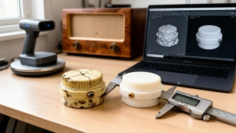
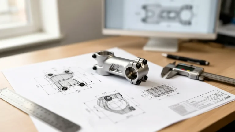
We have delivered over 7,000 projects across 40+ countries in 9+ years of operation — consumer products, industrial hardware, medical device components, and aerospace fixtures. See our custom brackets and mounts portfolio item — caliper-measured, modeled in SolidWorks, delivered as STL, 3MF, and STEP from a single order, ready for both 3D printing and CNC machining quotes.
File Formats Delivered with Every Order
Every custom cad design service order ships with STEP AP214 for CNC and injection molding vendors and a print-ready STL or 3MF for 3D printing. Complex Part orders add the native SLDPRT, and Assembly orders add SLDPRT and SLDASM; on a Single Part the native file is a $25 add-on. IGES and OBJ exports and dimensioned PDF or DWG drawings are add-ons priced in your quote.
Design for Manufacturing — Standard, Not Optional
We do not just model what you draw. We flag manufacturability issues before delivery as a standard part of every 3d cad modeling engagement: wall thickness violations for your target print process, draft angles for injection molds, minimum feature sizes for CNC, and clearance fits for mated assemblies. Refer to the SolidWorks official part modeling documentation for the part modeling standards our engineers work against.

Clear Scope, Reliable Delivery — Verified Across 7,000 Orders
Rated 4.9 out of 5 across 4,470+ verified Fiverr reviews — not an aspirational claim. Complex assemblies with ten or more components are quoted after an honest scope review. We clarify every ambiguity before work begins, so your included revision rounds are used for refinement, not correction of misunderstood requirements.
Pricing
Our mechanical design services are priced as three flat-rate packages: Single Part at $79, Complex Part at $149, and Assembly at $289 for up to five parts. Larger projects are quoted as a Custom Project. Full breakdown at Pricing.
Why SolidWorks Specifically
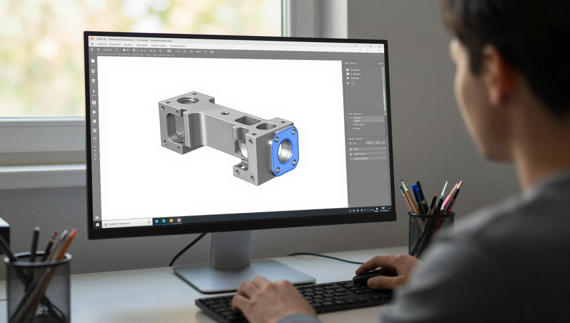
SolidWorks is the industry standard for mechanical product design because its feature-based parametric modeling creates geometry that is directly interpretable by CAM software, FEA solvers, and PDM systems. When you outsource to a service that models in a consumer-grade tool and exports to SolidWorks format, you lose the feature tree — which means no editability, no design intent, and no clean version history. Our solidworks modeling service delivers the native SLDPRT (included with Complex Part and Assembly) with a logical feature tree organized by design intent, not by the order clicks were made. Every suppression state, every sketch relation, every configuration is intentional and documented.
What to put in the brief
Overall dimensions, the material, the manufacturing method, and every mating interface with its dimensions. A photo or sketch of the part, and the printer or machine it is made on. The more of this the brief states, the fewer questions before the quote.
What you get
- Native SolidWorks files: SLDPRT for parts, SLDASM for assemblies, SLDDRW when drawings are ordered.
- STEP for any other CAD system or a CNC shop, and STL for printing.
- Flat-pattern DXF for sheet-metal parts, with the K-factor stated (0.44 for 1.5 mm mild steel, 0.40 for 1.0 mm aluminum).
- A fully defined feature tree, named features, and design intent you can edit.
- Print orientation notes and a material recommendation when the part is printed.
Technical drawings, renders and extra formats are add-ons, priced in your quote.
Manufacturing rules we design to
Injection molding: 1 degree of draft minimum, wall thickness uniform within 10 percent, no undercuts without a slide. CNC machining: internal corner radius 1.5 to 3 mm, pocket depth no more than four times the tool diameter. Sheet metal: bend radius at least one material thickness, holes at least 2.5 thicknesses from a bend. Drawings: ASME Y14.5 or ISO 1101 GD&T, ISO 2768-mK general tolerances, first- or third-angle projection and units stated in the title block.
Start Your CAD Order
Upload your sketch, PDF, photograph, or reference file at the quote page and receive a quote within 24 hours. Questions before ordering, or need a scope review before committing? Reach our team directly at Contact.
Frequently Asked Questions
How do revisions work?
Each round is one consolidated list of changes. Fixes to anything that is our error are always free and never count as a round.