A fully custom electronics enclosure designed in SolidWorks — engineered to fit your exact PCB dimensions. Features include ventilation holes for thermal management, precision cutouts for USB, charging, and port access, and a base-and-lid assembly secured by screws for clean professional packaging. Optional custom logo embossed or engraved on the lid surface. Printed in PLA for standard use or ABS for heat resistance and mechanical strength. Delivered as STEP, STL, and SolidWorks source files — fully manufacturing-ready for both 3D printing and injection molding tooling. Show More
A custom enclosure design for electronics is one of the most common and most specification-critical projects in 3D printing — the PCB must fit with clearance on all sides, every port must align with the board’s connector positions to within 0.5mm, and the thermal management design must prevent heat buildup during operation. This project covers the full design and delivery of a custom PCB project box for a client’s custom microcontroller board.
Project Specifications
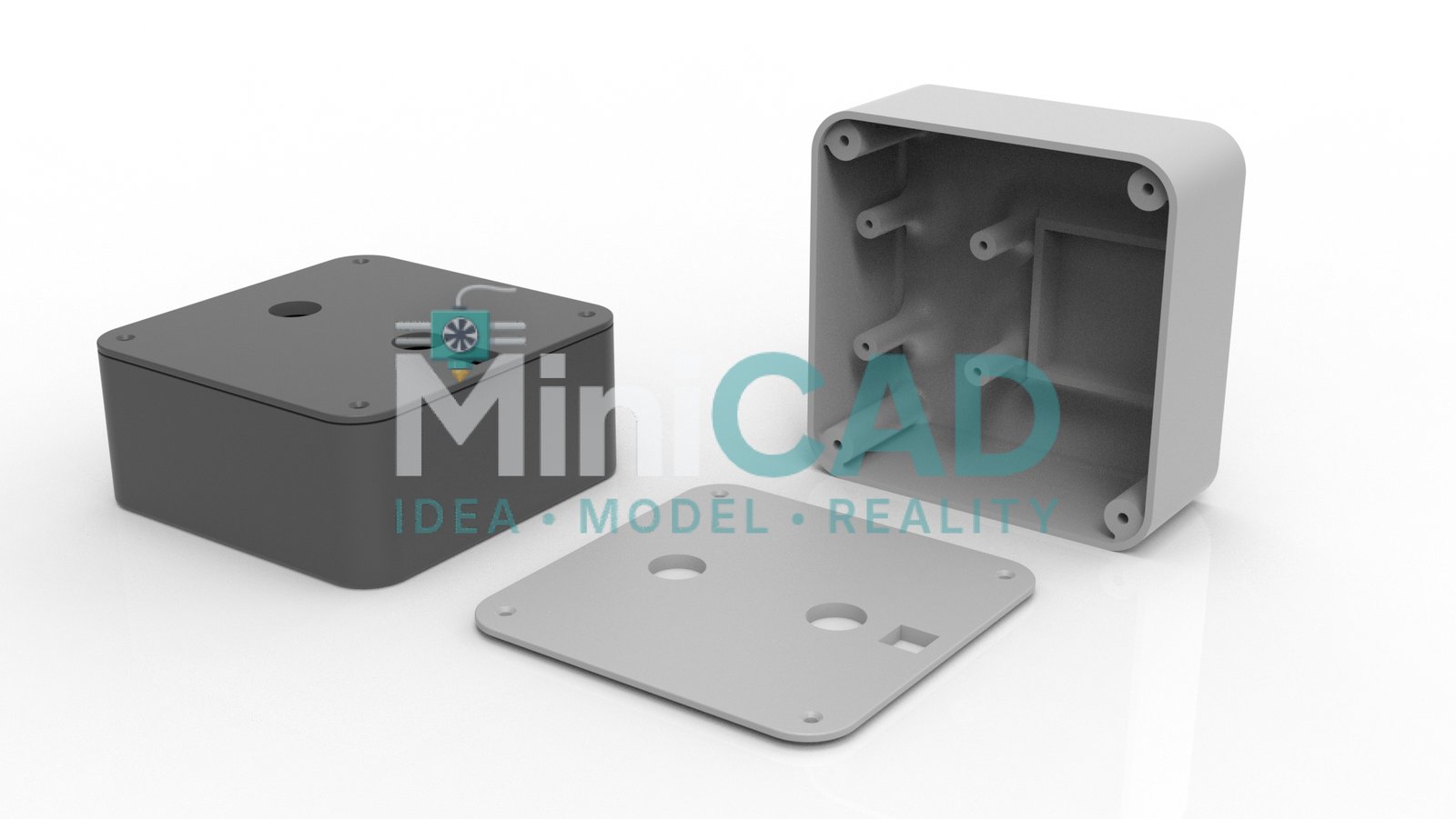
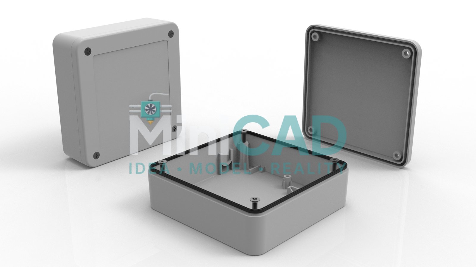
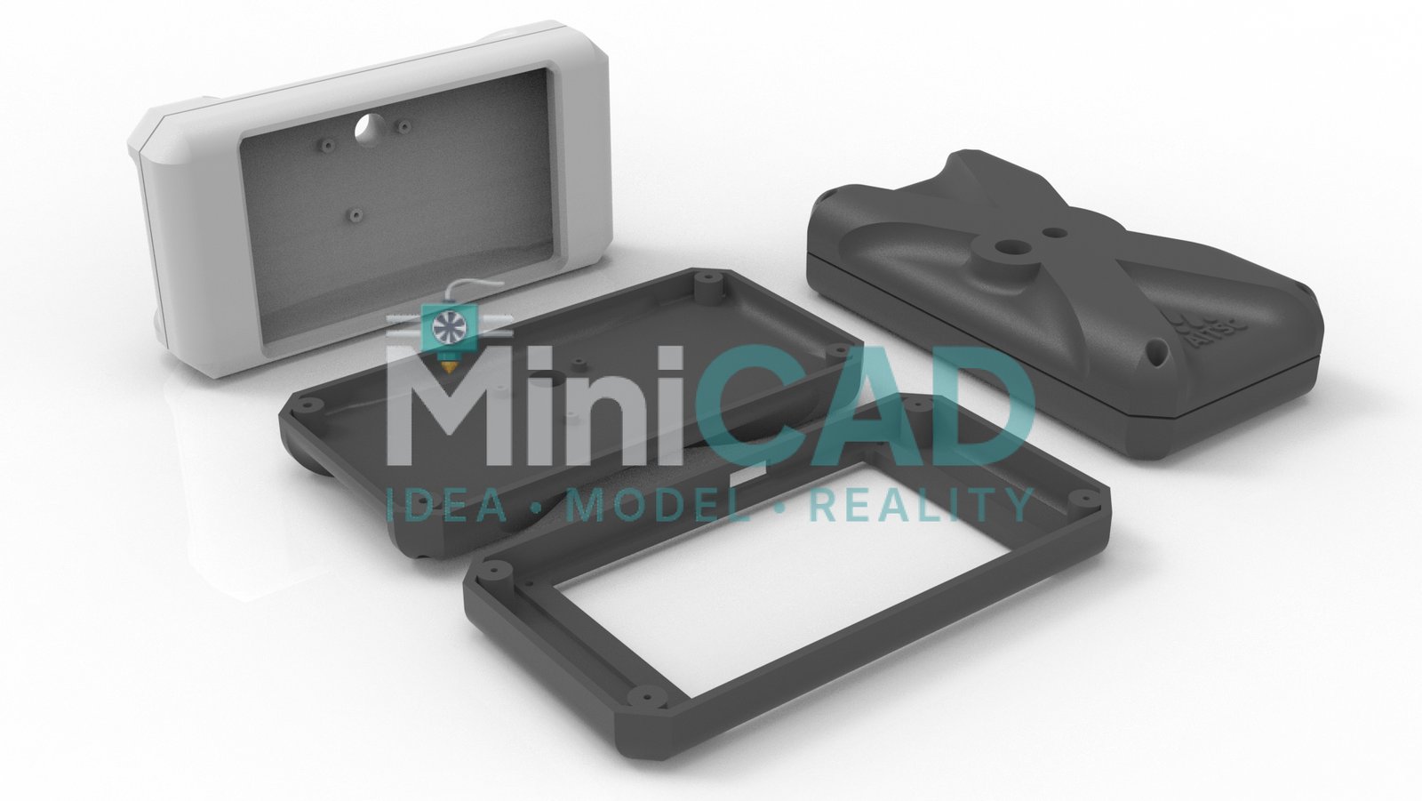
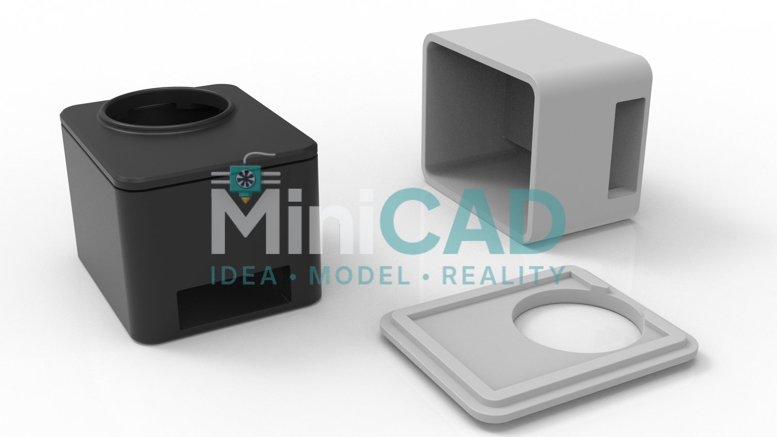
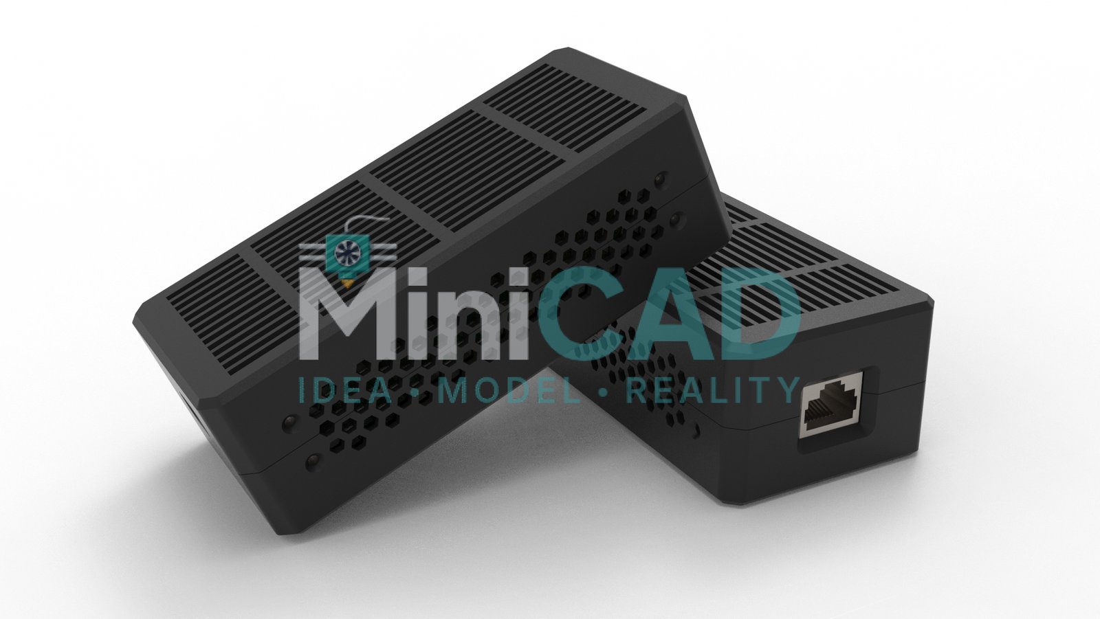
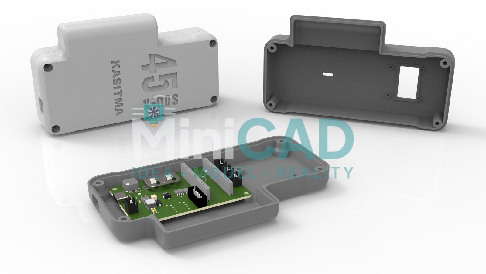
The client supplied a PCB datasheet with mounting hole positions, connector locations, and component height map. The enclosure required: four M3 standoff boss features at the PCB mounting hole positions, precision cutouts for USB-C, HDMI, and a 3.5mm audio jack, a ventilation slot array on the top face above the main processor, and a two-part base-and-lid assembly secured by four M2.5 screws in recessed boss features. Optional logo embossing on the lid face. Our solidworks modeling service built every feature directly from the PCB datasheet dimensions.
Tolerance Engineering for Port Cutouts
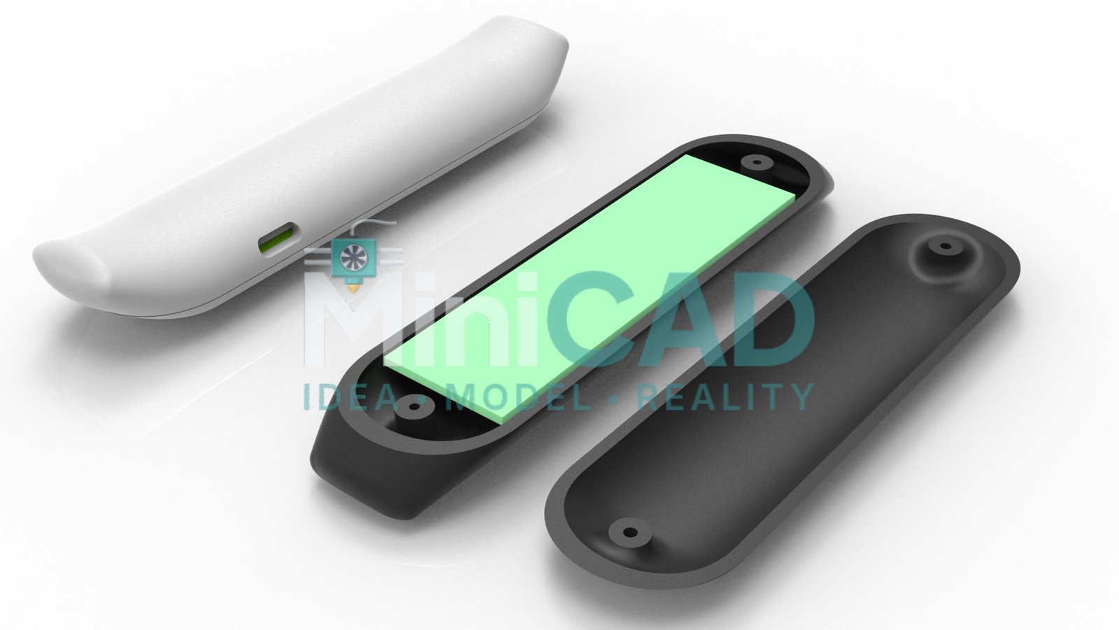
Port cutouts for USB-C and HDMI connectors were modeled at nominal PCB position plus 0.3mm clearance on each edge — tight enough for professional appearance, generous enough to accommodate FDM dimensional variance at 0.2mm layer height. The standoff bosses were designed at 3.1mm internal diameter for M3 heat-set inserts rather than self-tapping threads, providing better thread engagement in PLA. This is part of our standard cad design for 3d printing tolerance protocol for electronics enclosures.

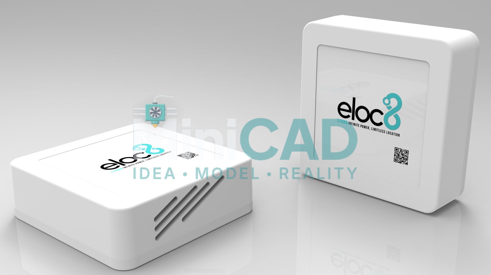
Ventilation and Thermal Management
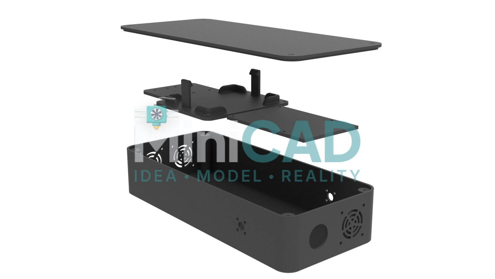
The ventilation pattern was designed as a staggered slot array positioned directly above the processor IC, with slot width and spacing determined by the required open-area ratio (minimum 25% for passive cooling at the client’s stated ambient temperature). Slot geometry was verified against our stl file design service minimum feature size guidelines — 0.8mm slot width as the minimum for clean FDM printing at 0.4mm nozzle diameter with no wall sagging between slots.
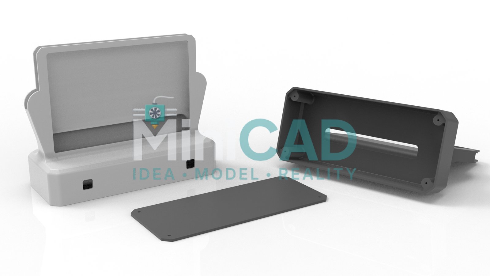
Manufacturing-Ready for Both 3D Printing and Injection Molding
The client requested files suitable for both 3D printing a development batch and injection molding a production run. The SolidWorks model was designed with 1.5-degree draft angles on all vertical walls and 0.5mm corner radii on all internal features — standard injection molding requirements that do not affect 3D print quality. Our 3d printing design service delivered STEP AP214 for the mold quotation and binary STL for the development print simultaneously.
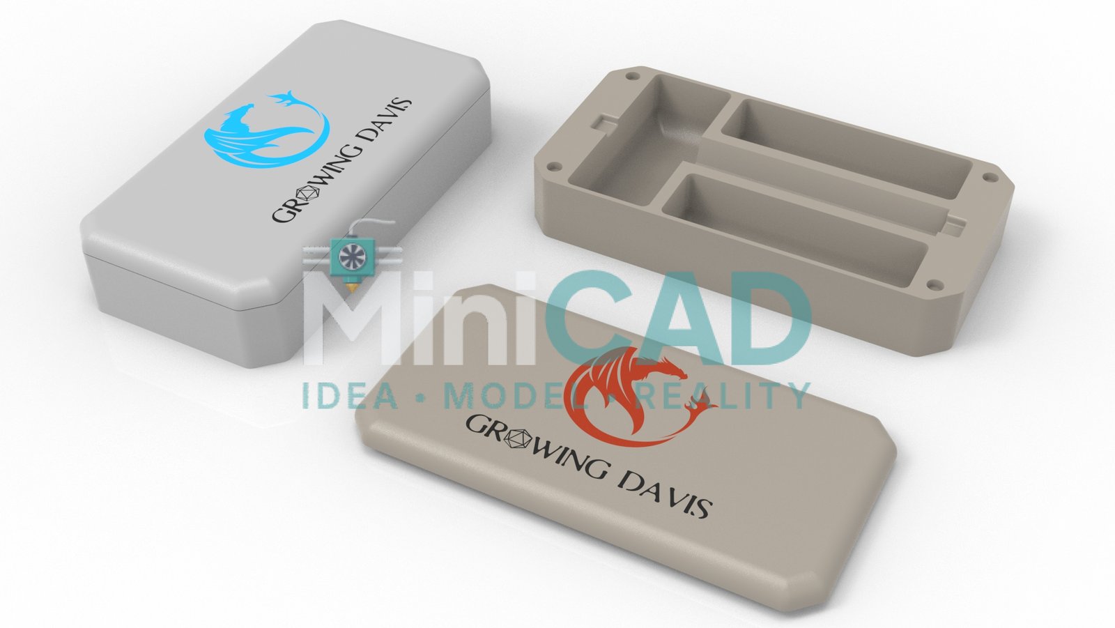
Design for Assembly and Serviceability
An electronics enclosure that cannot be opened and re-closed cleanly is a failed design, regardless of how well it fits the PCB. This enclosure was designed with screw boss geometry that accepts M2.5 heat-set inserts pressed into the PLA after printing — providing metal thread engagement that survives repeated open-and-close cycles without thread strip-out, which is the most common failure mode for self-tapping screws in 3D-printed bosses. The lid alignment was handled by two 2mm guide pins on the base mating with corresponding 2.1mm guide holes in the lid — ensuring the lid seats without rotation and the port cutouts remain aligned with the PCB connectors after every reassembly. This serviceability engineering is part of every custom enclosure design for electronics order at MiniCAD — the enclosure must survive field use, not just the first assembly. Our cad design for 3d printing approach validates every assembly interface — thread engagement, guide pin fit, and lid seating — before the STL is exported to the client.
Design Your Electronics Enclosure
Supply your PCB datasheet and we engineer the enclosure around it. Our SolidWorks 3D CAD modeling service handles PCB enclosures, sensor housings, and control panel boxes. Start at Order. Pricing from $34 at Pricing.