
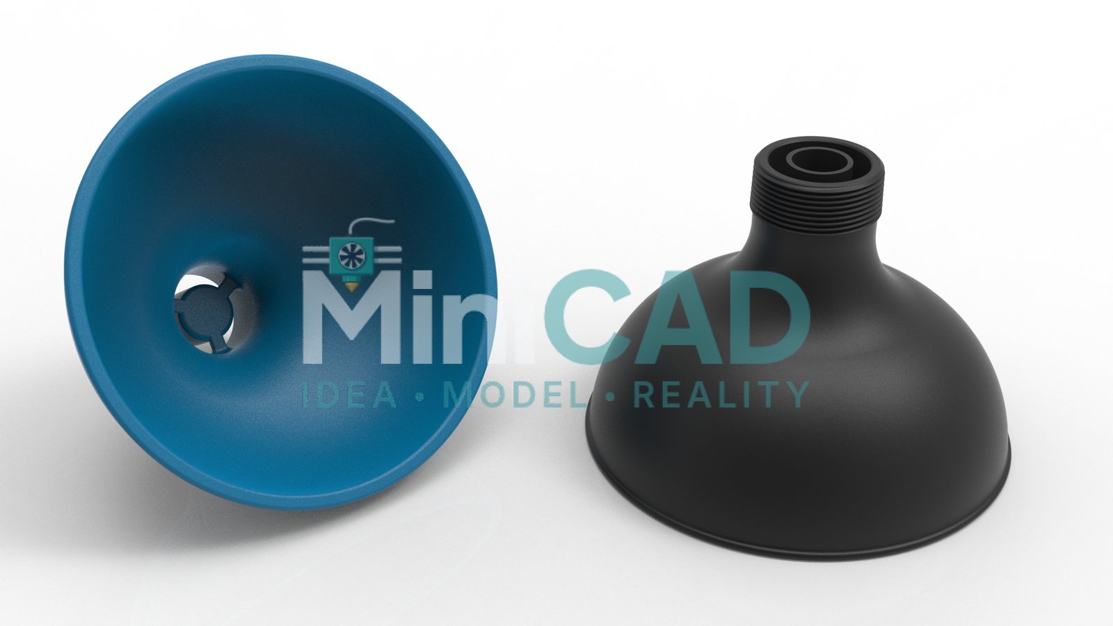
Precision flow components designed in SolidWorks to exact client specifications — nozzles, diffusers, reducers, adapters, and custom manifolds. Each part is modeled to match your inlet and outlet dimensions precisely, whether bridging two different pipe sizes, distributing flow across multiple outlets, or collecting multiple inlets into a single output. Suitable for air, gas, liquid, and dust extraction systems. Printed in PLA for light-duty use, PETG for chemical resistance, ABS for heat tolerance, or high-performance materials such as carbon fiber and PEEK for demanding industrial applications. Every part is delivered print-ready as STEP, STL, and SolidWorks source files — ready for immediate 3D printing or direct use in your system. Show More
Precision flow components are among the most demanding applications of cad design for 3d printing — a nozzle or diffuser with incorrect internal bore — a nozzle or diffuser with incorrect internal bore dimensions will produce flow rates, pressure drops, and velocity profiles that do not match the design intent, regardless of print quality. This project shows our full cad design for 3d printing workflow applied to a nozzle and diffuser manifold system, from client specification to print-validated delivery.
Project Overview
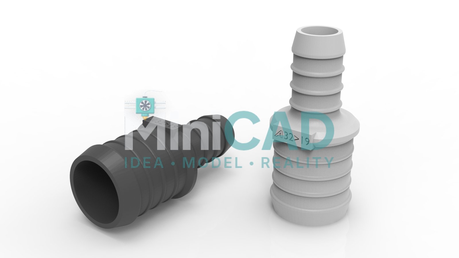
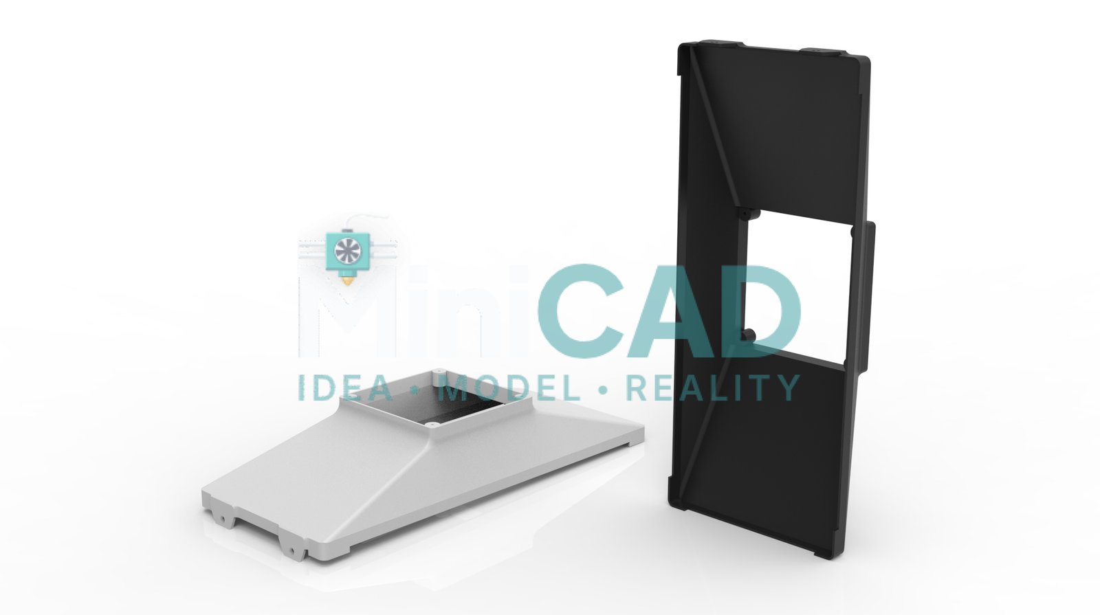
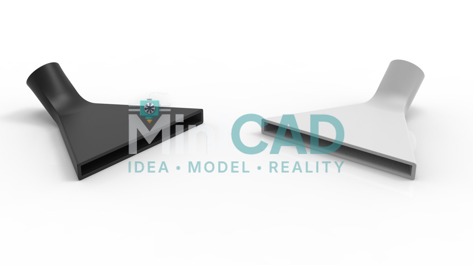
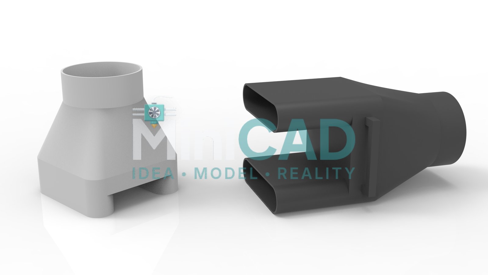
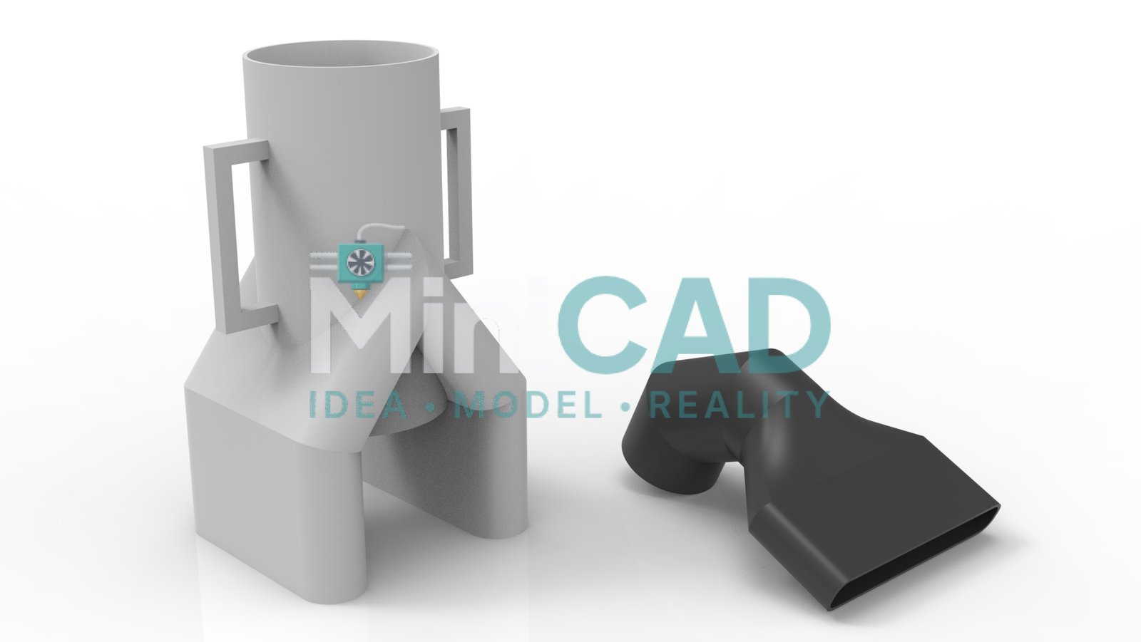
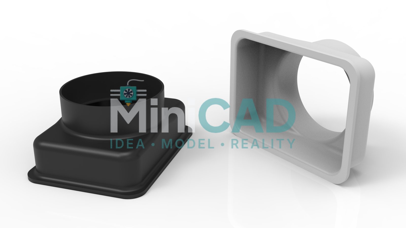
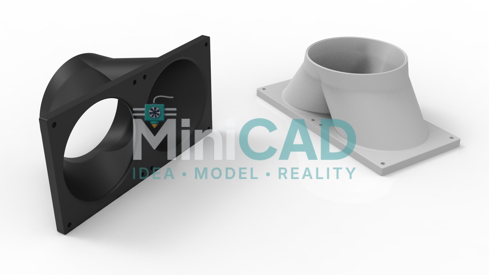
The client needed a custom diffuser to transition a 50mm circular duct to a 120mm × 40mm rectangular outlet — bridging two incompatible existing duct sections in a workshop dust extraction system. A second component was a three-way manifold distributing airflow from a single 75mm inlet to three 40mm circular outlets at equal pressure. Both parts needed to print without support material and fit onto existing push-fit duct fittings with a 0.3mm clearance tolerance.
SolidWorks Modeling for Flow Geometry
Both parts were modeled using SolidWorks lofted and swept features to generate smooth internal transitions — critical for maintaining laminar flow and minimizing pressure drop. The diffuser transition profile was designed as a guided loft between the circular and rectangular profiles with three intermediate guide curves to control wall angle at each cross-section. Our stl file design service export workflow validated wall thickness along the loft path before the final STL was generated, ensuring no wall dropped below 1.8mm at any point.

Material Selection and Print Settings
The dust extraction environment required moderate heat and chemical resistance. We specified PETG for both parts — better than PLA for sustained temperatures above 60°C and resistant to the light solvents present in the workshop environment. Our 3d printing design service recommendation included 3 perimeter walls at 0.4mm nozzle, 30% gyroid infill for pressure resistance, and a 0.2mm layer height for dimensional accuracy on the push-fit collars. Print orientation was specified with the outlet collar face down to eliminate support from the mating surface.
Files Delivered
The client received STEP AP214 for both parts, binary STL pre-oriented for the recommended print setup, and native SolidWorks SLDPRT files with the full feature tree. The prototype design service bundle also included a one-page print settings sheet specifying material, orientation, layer height, infill, and expected dimensional outcome for both parts.
Need a Custom Flow Component?
Custom nozzles, reducers, adapters, manifolds, and diffusers for air, gas, liquid, and dust extraction systems are a standard part of our STL file design and repair service. We model to your exact inlet and outlet dimensions and verify wall thickness and flow geometry before delivery, in any printable material. Start at Order or see pricing at Pricing.
Design Validation for Flow Performance
Diffuser geometry that appears correct in a 3D viewer may still produce turbulence or pressure loss exceeding the design target. For this project, we validated the diffuser transition angle — ensuring wall divergence did not exceed 7 degrees per side at any cross-section, the empirical threshold for attached flow in low-velocity air systems. This is standard practice in our cad design for 3d printing workflow for fluid-carrying components: geometry is reviewed against basic fluid mechanics principles before the STL is exported. The manifold equal-distribution geometry was verified by checking cross-sectional area at each branch — all three outlets were within 1.5% of equal area, producing balanced flow distribution without a control valve. This engineering review is what distinguishes a purpose-built custom 3d printing design from a basic extrude-and-export workflow, and it is applied to every pressure-bearing or flow-carrying component we model through our STL file design and repair service.

