
Custom brackets and mounting parts designed in SolidWorks and AutoCAD — built to your exact measurements, taken directly from your existing hardware using caliper precision. No standard bracket fits every situation. Whether you need a wall mount, camera holder, pipe clamp, sensor bracket, shelf support, or a one-off fixture for a special application, each part is modeled from scratch to guarantee a first-time fit. Every design is verified against your dimensions before delivery. Delivered as STL for direct slicing, 3MF for full print settings, and STEP for editing or manufacturing. Suitable for home, workshop, robotics, electronics mounting, automotive, and industrial use.
When a standard bracket does not exist for your application, the only reliable solution is outsource cad design — and this project is a precise example of what that process delivers. A client brought us existing hardware with no original CAD files, a set of caliper measurements, and a clear fit requirement. We built every bracket from scratch in SolidWorks, verified every critical dimension against the provided measurements, and delivered print-ready files the same day.
Project Scope and Client Requirements
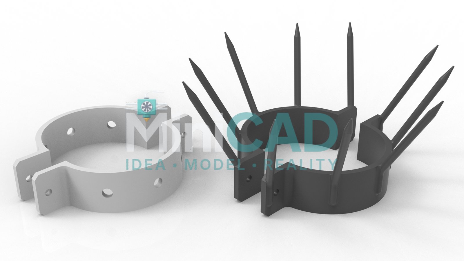
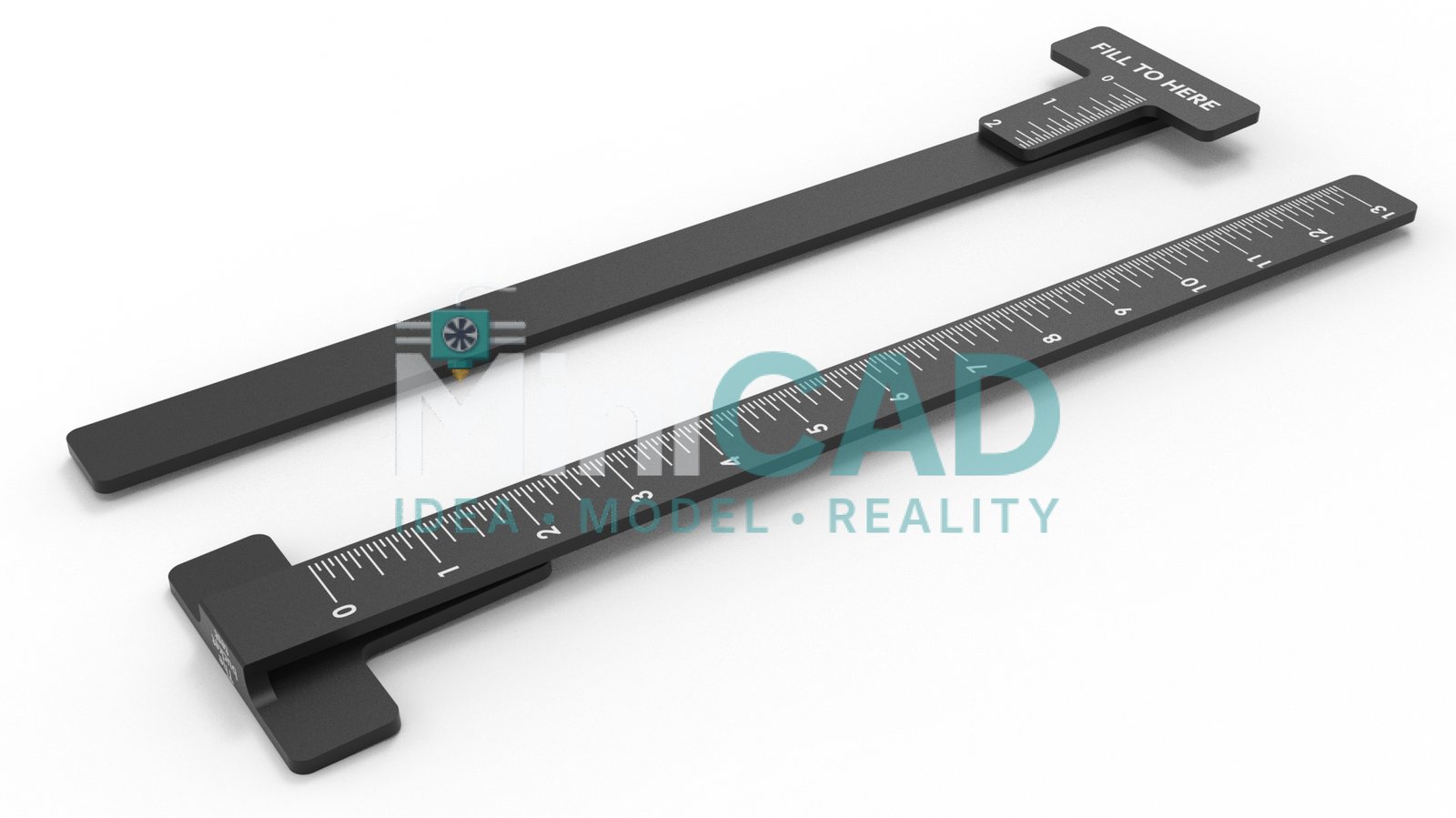
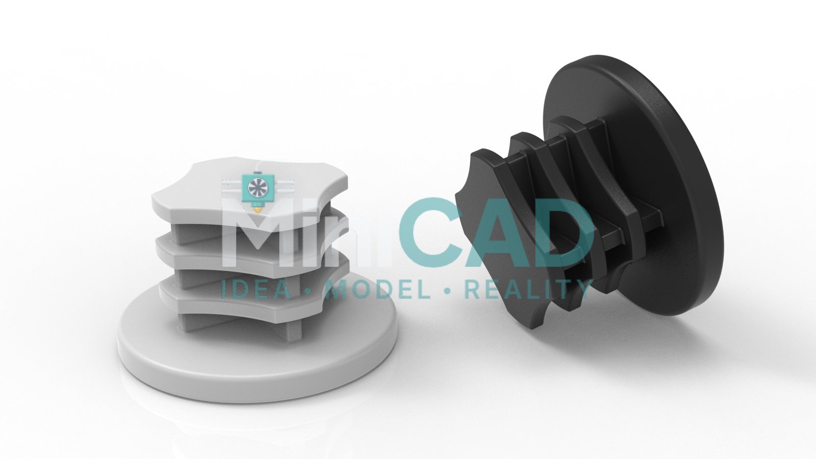
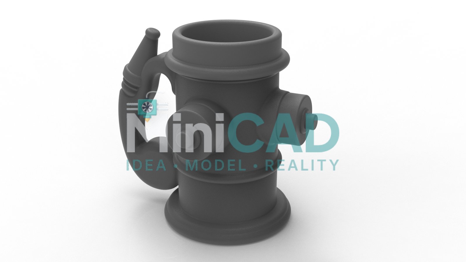
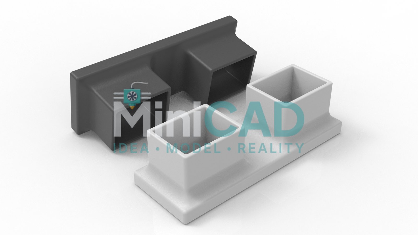
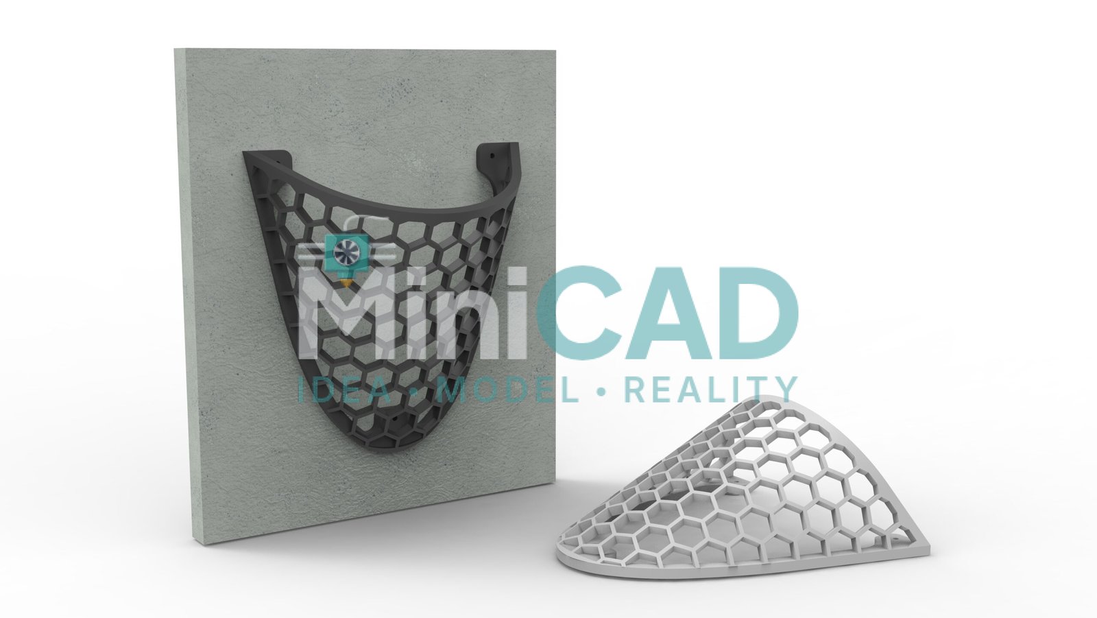
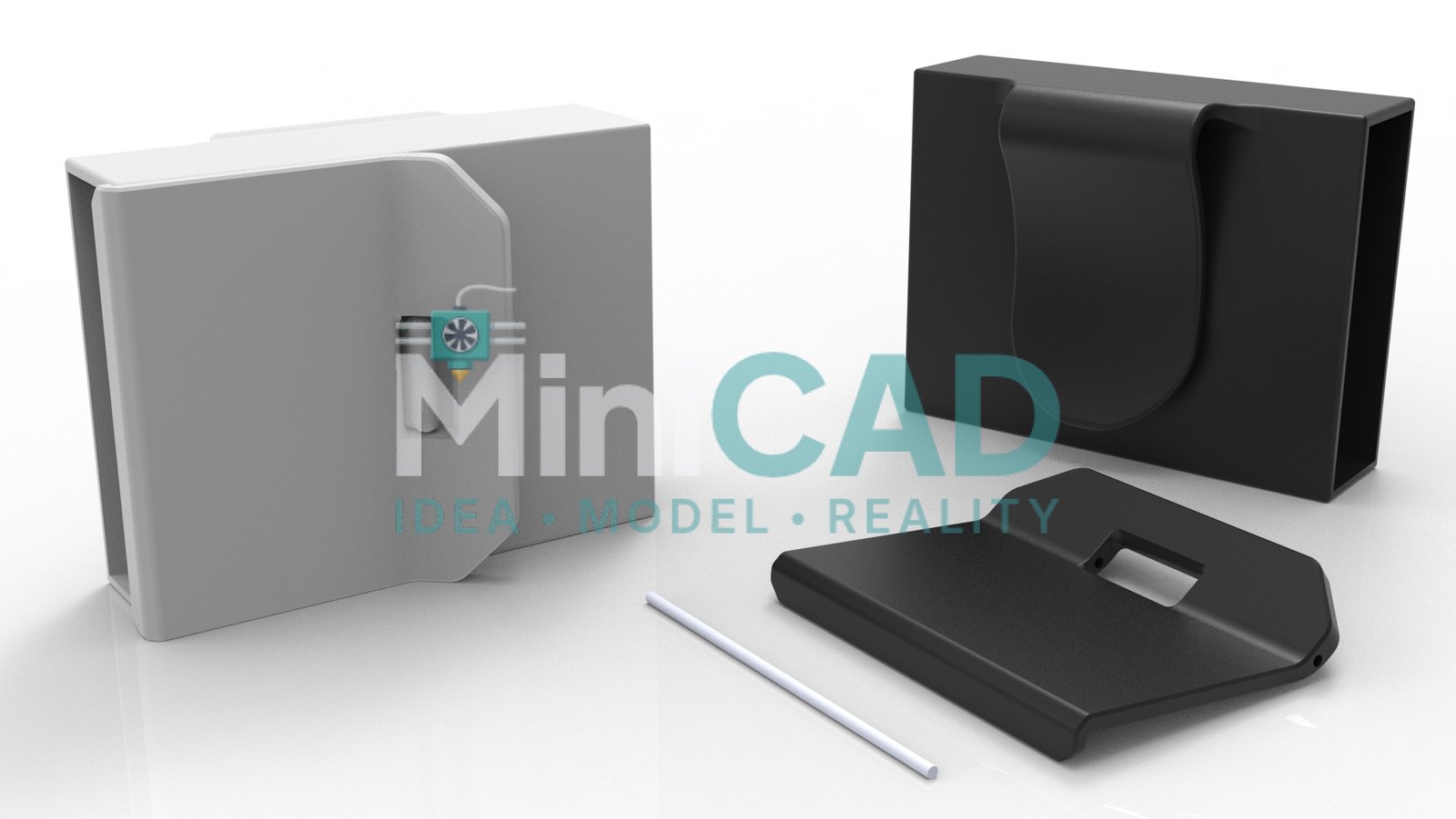
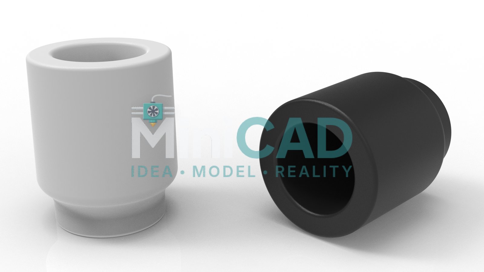
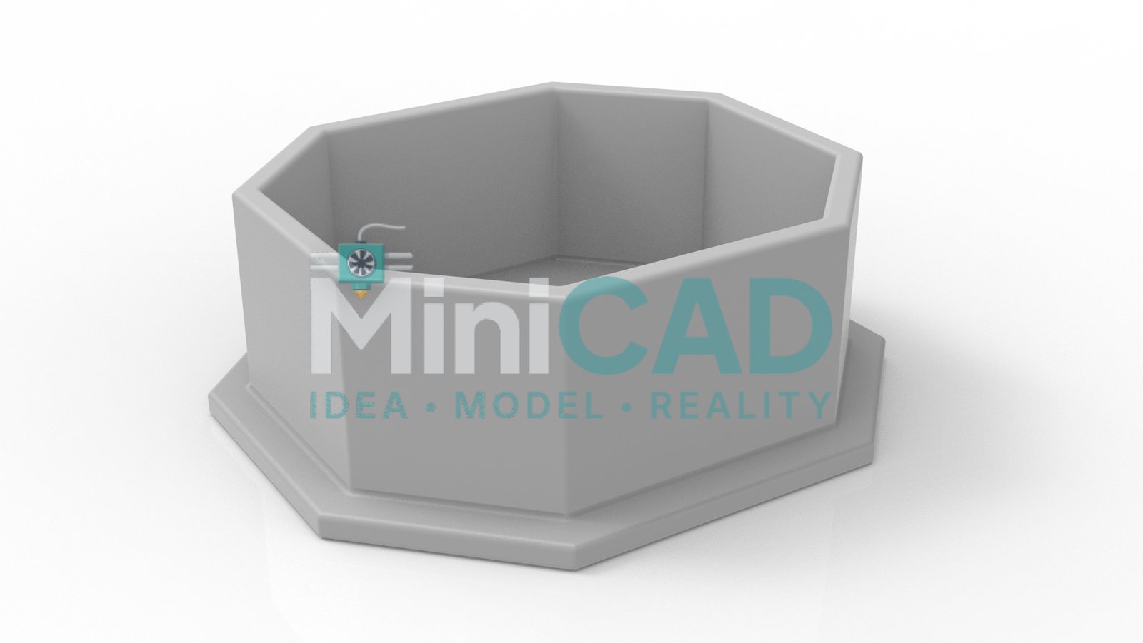
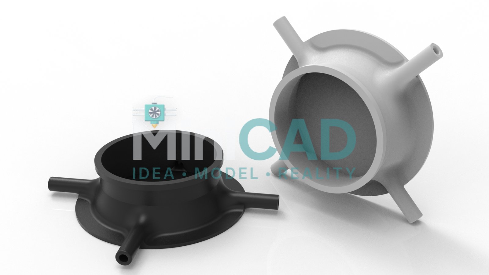
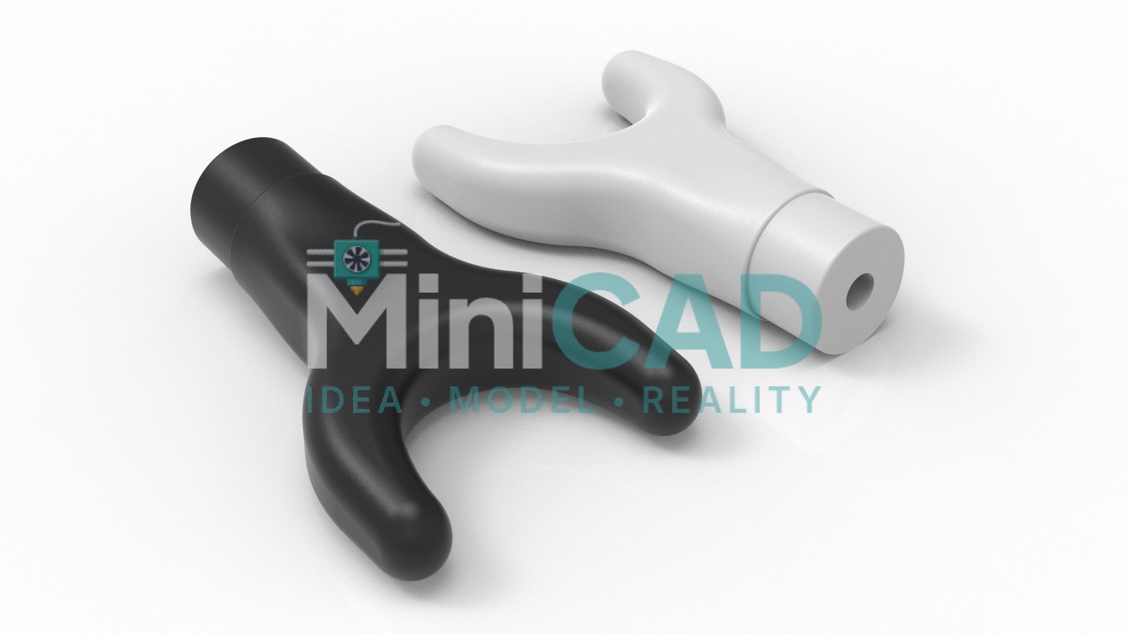
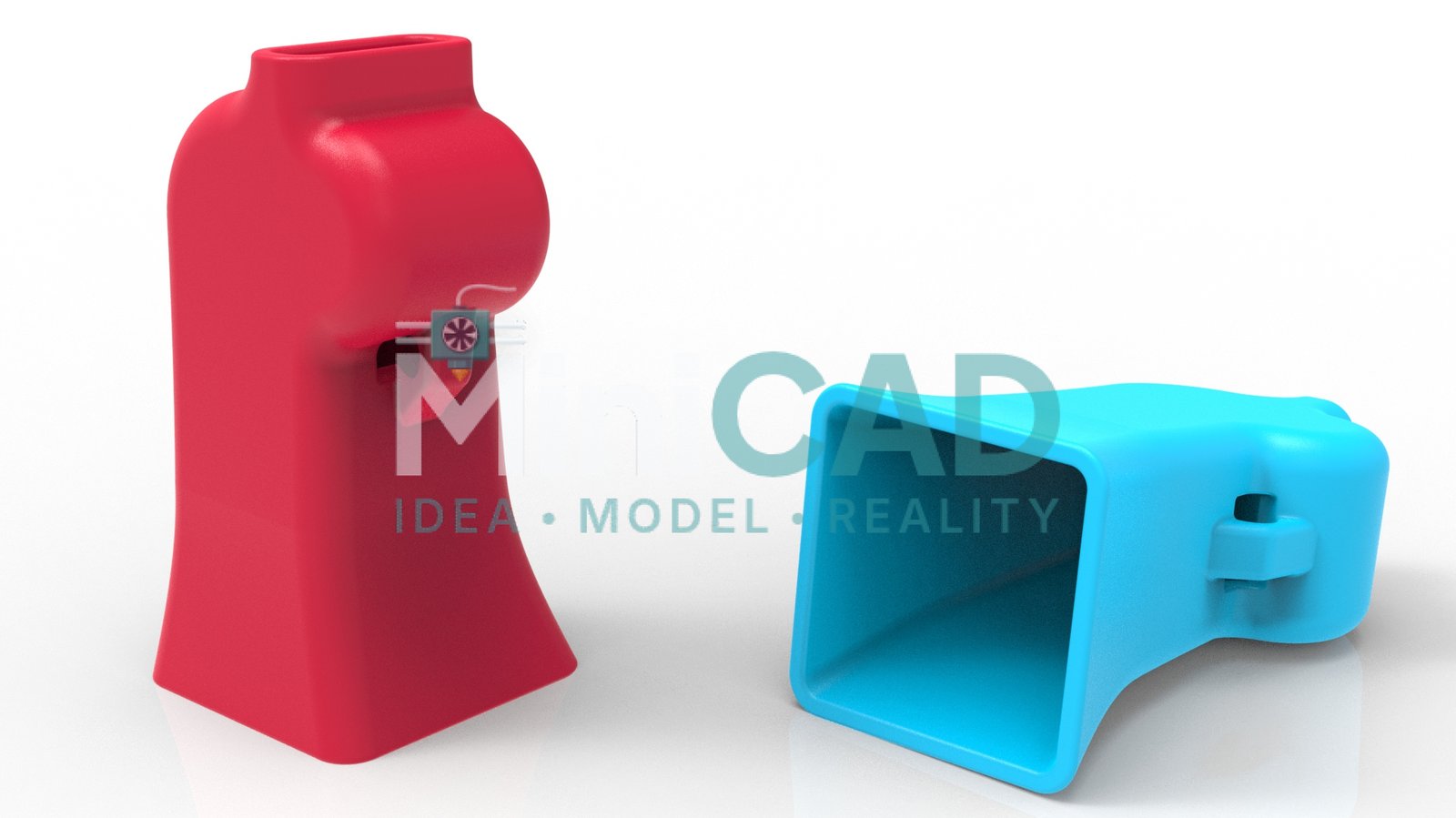
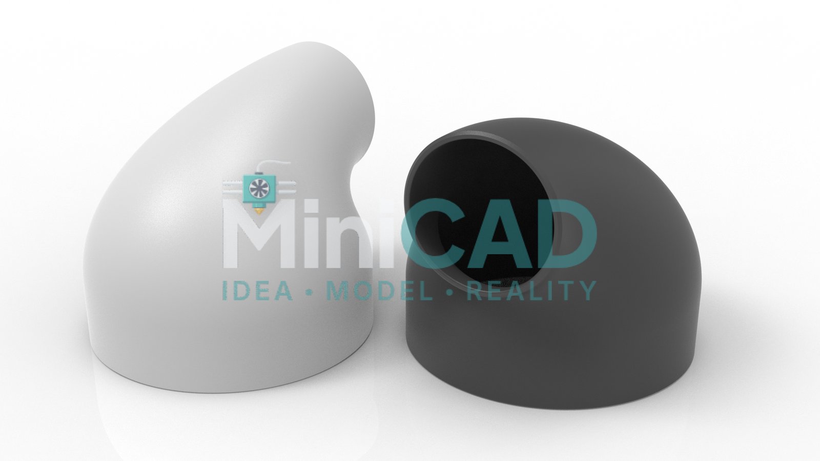
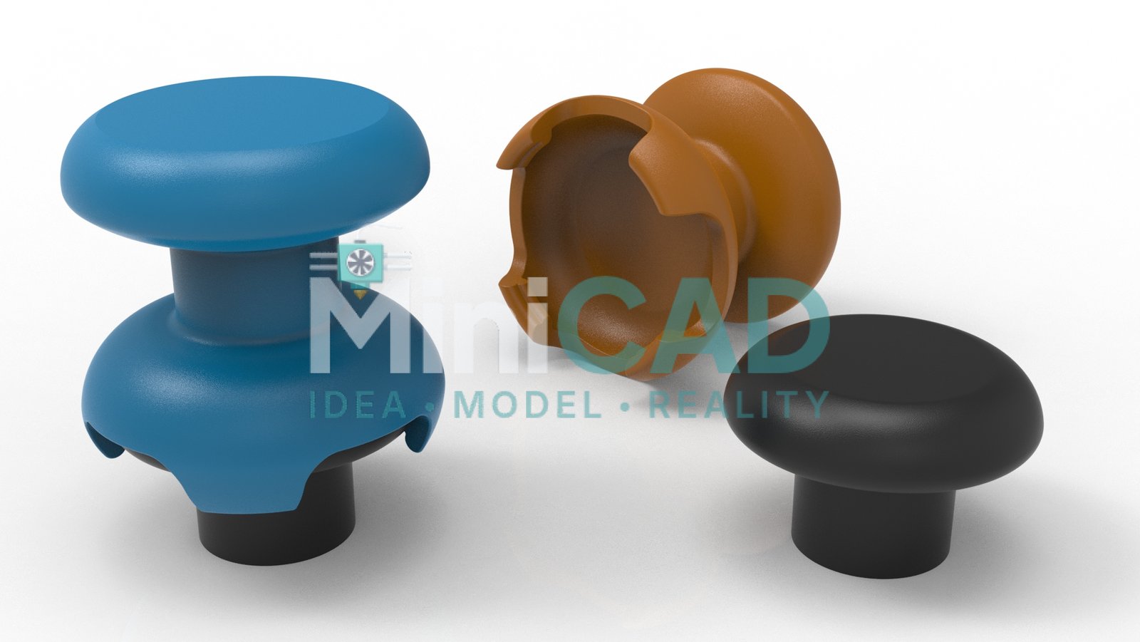
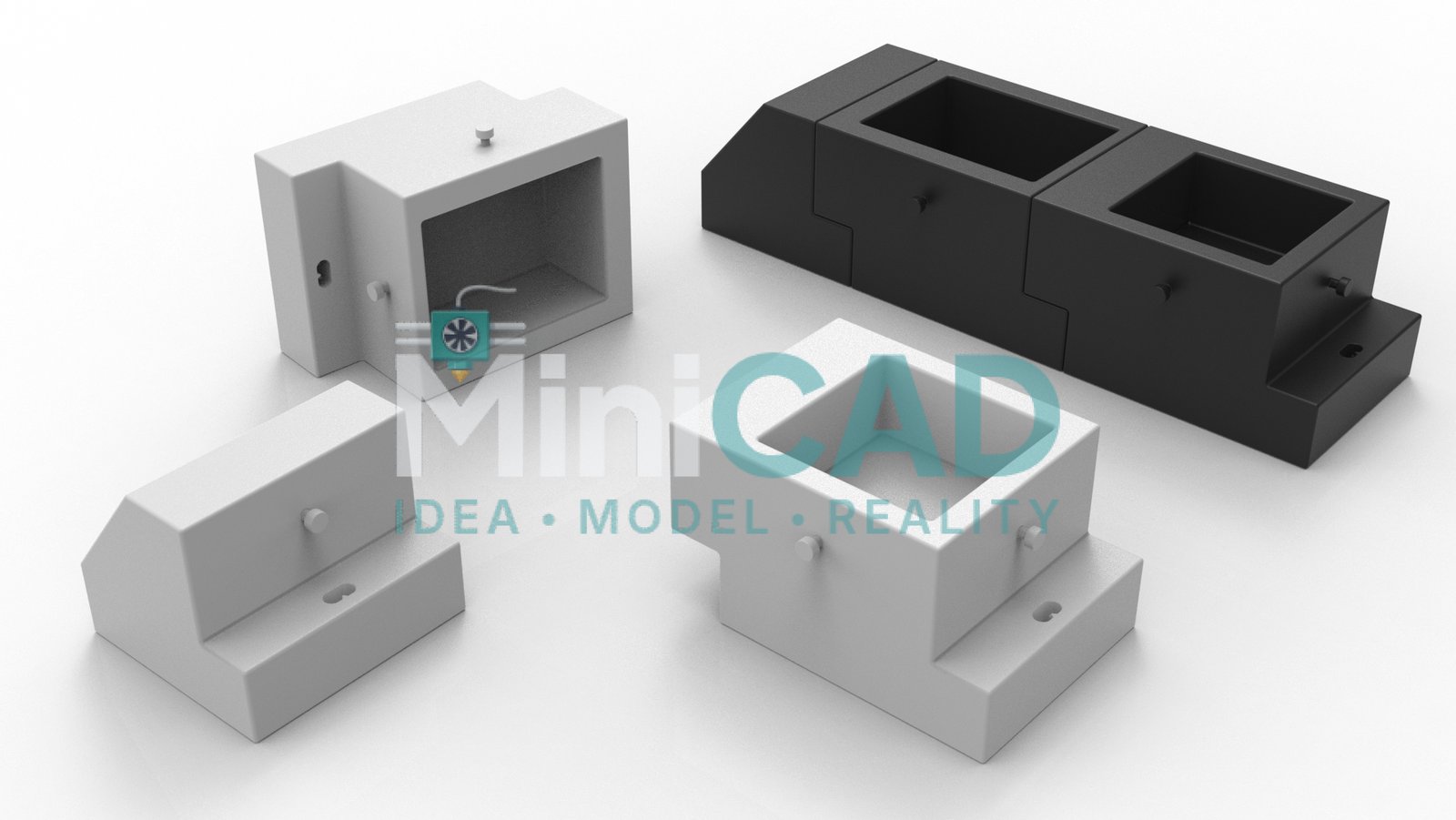
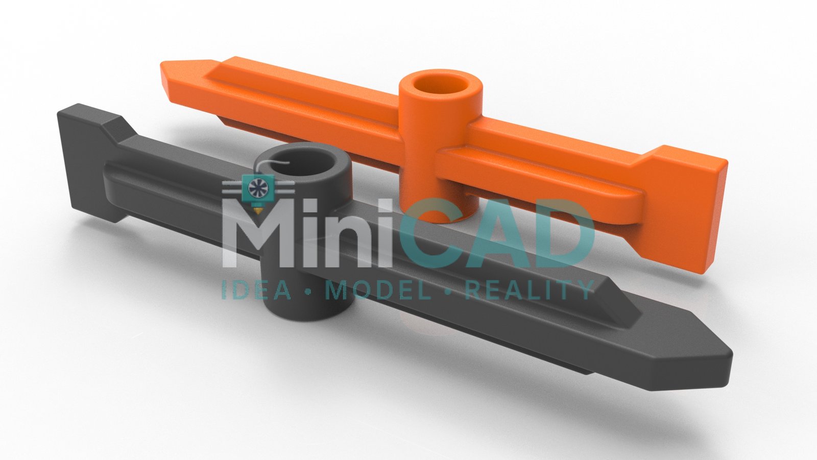
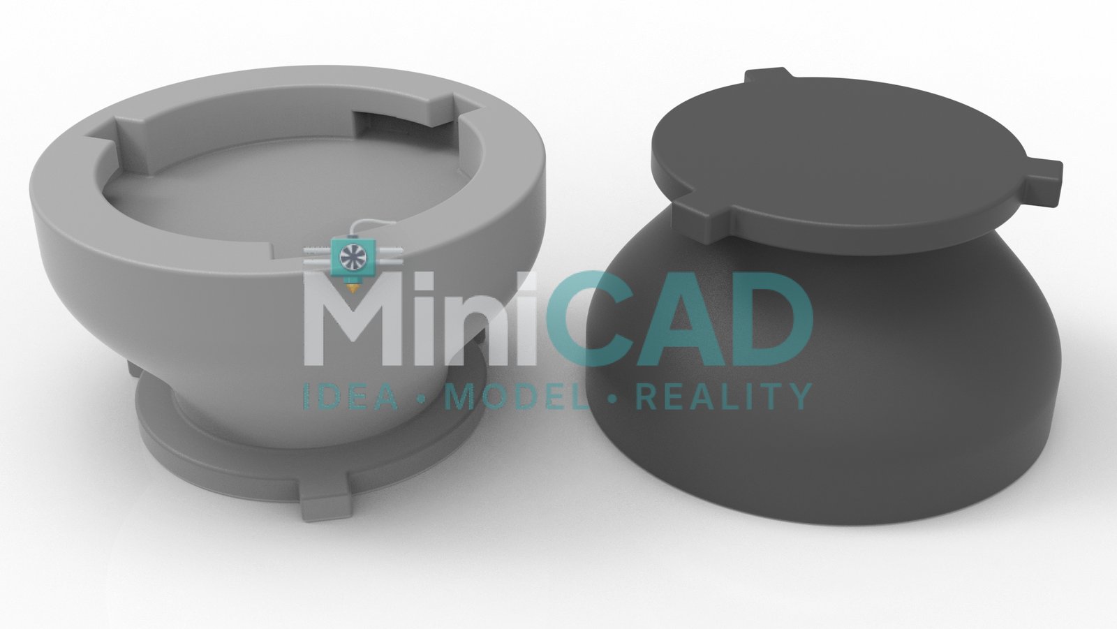
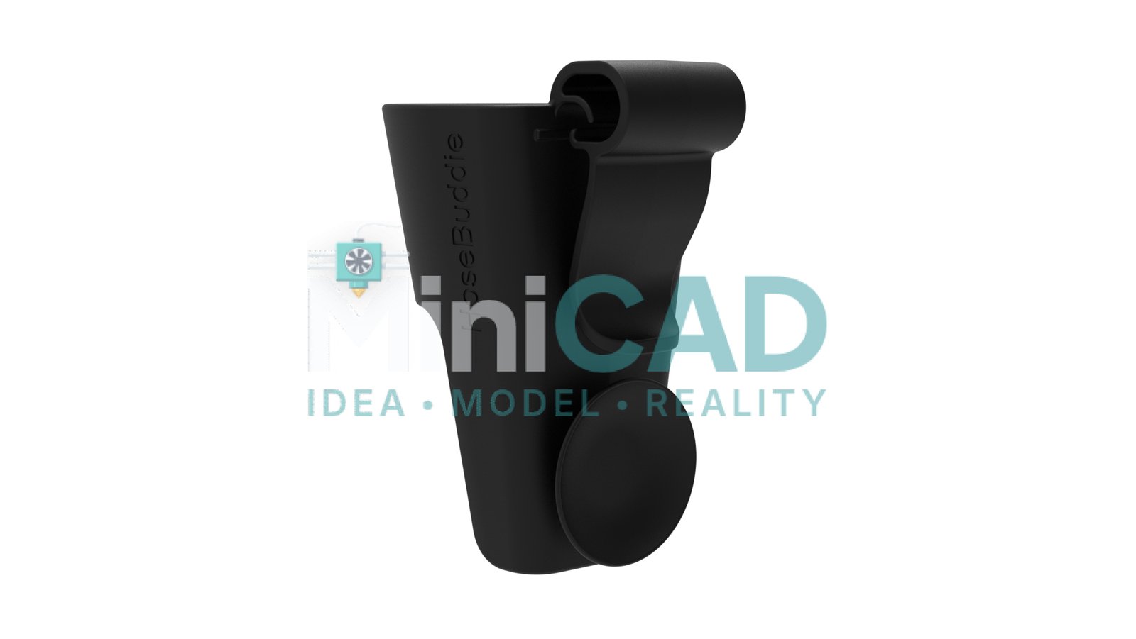
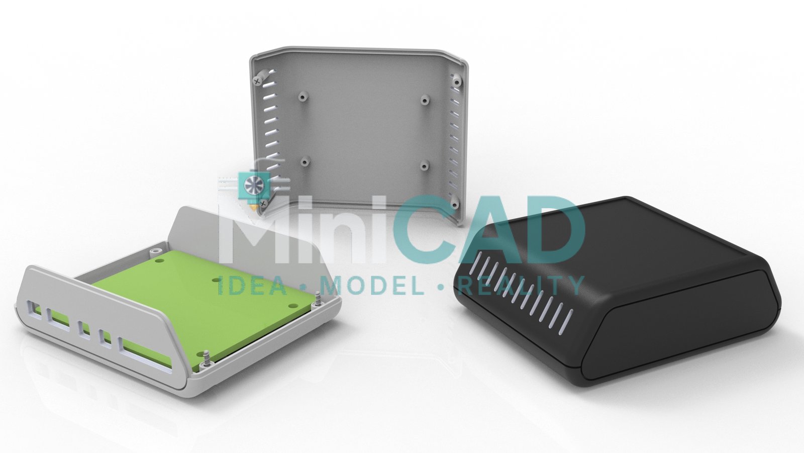
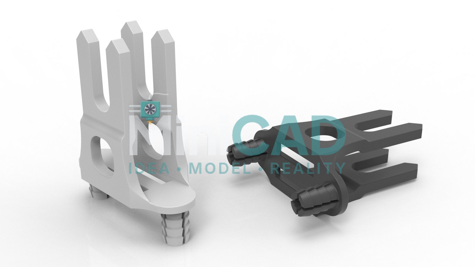
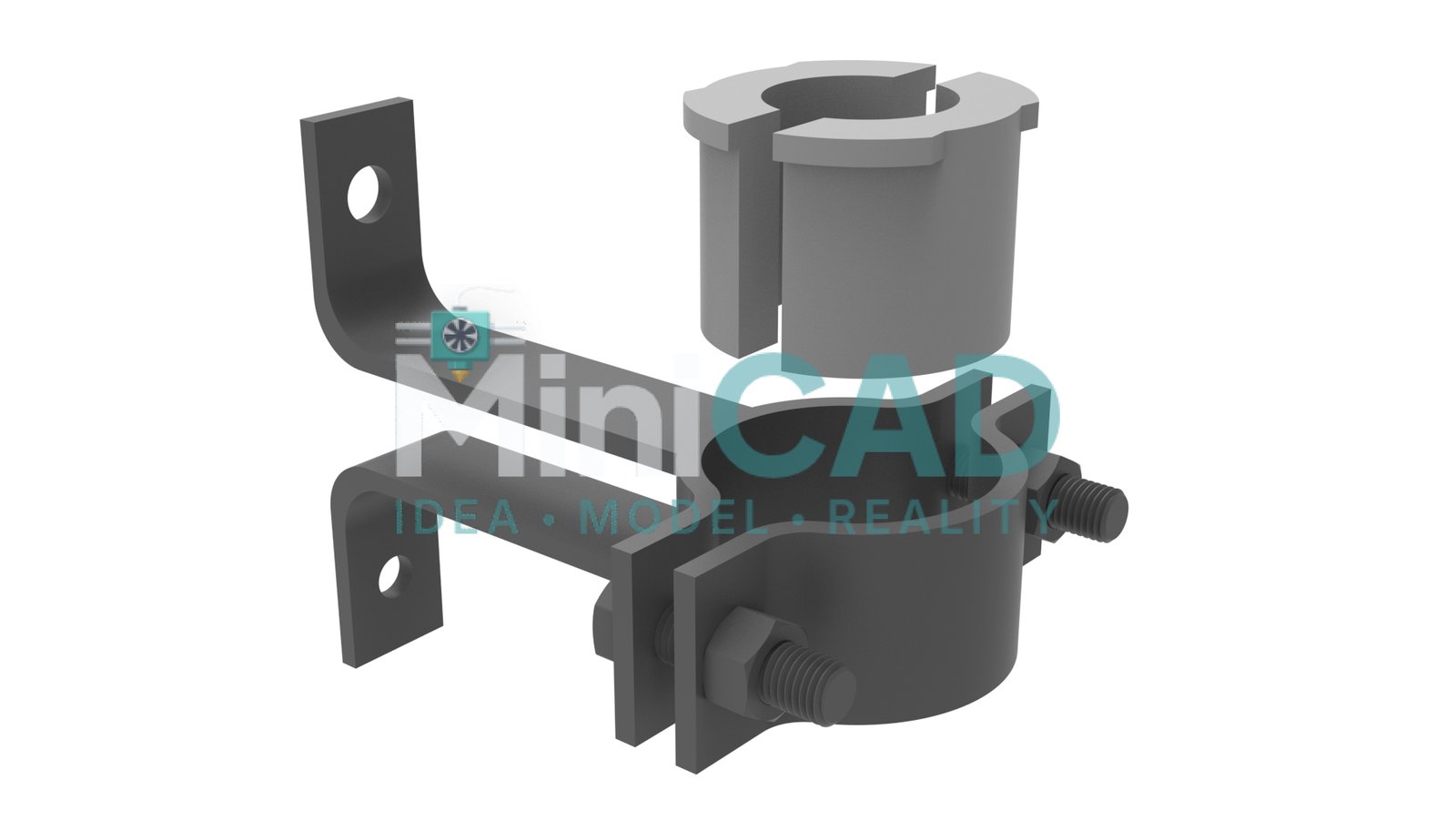
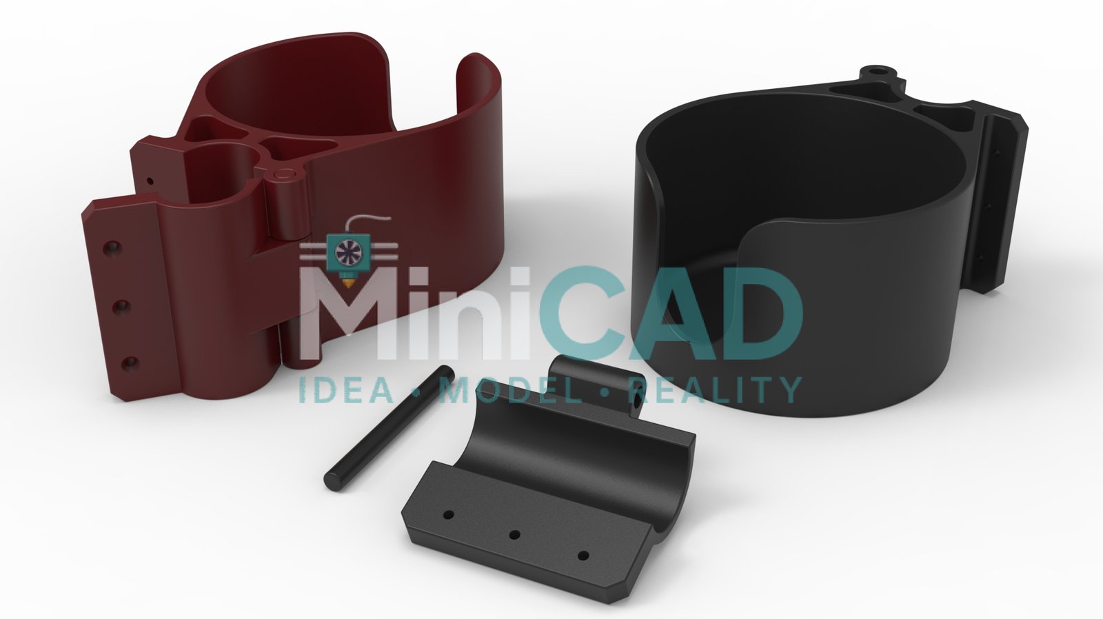
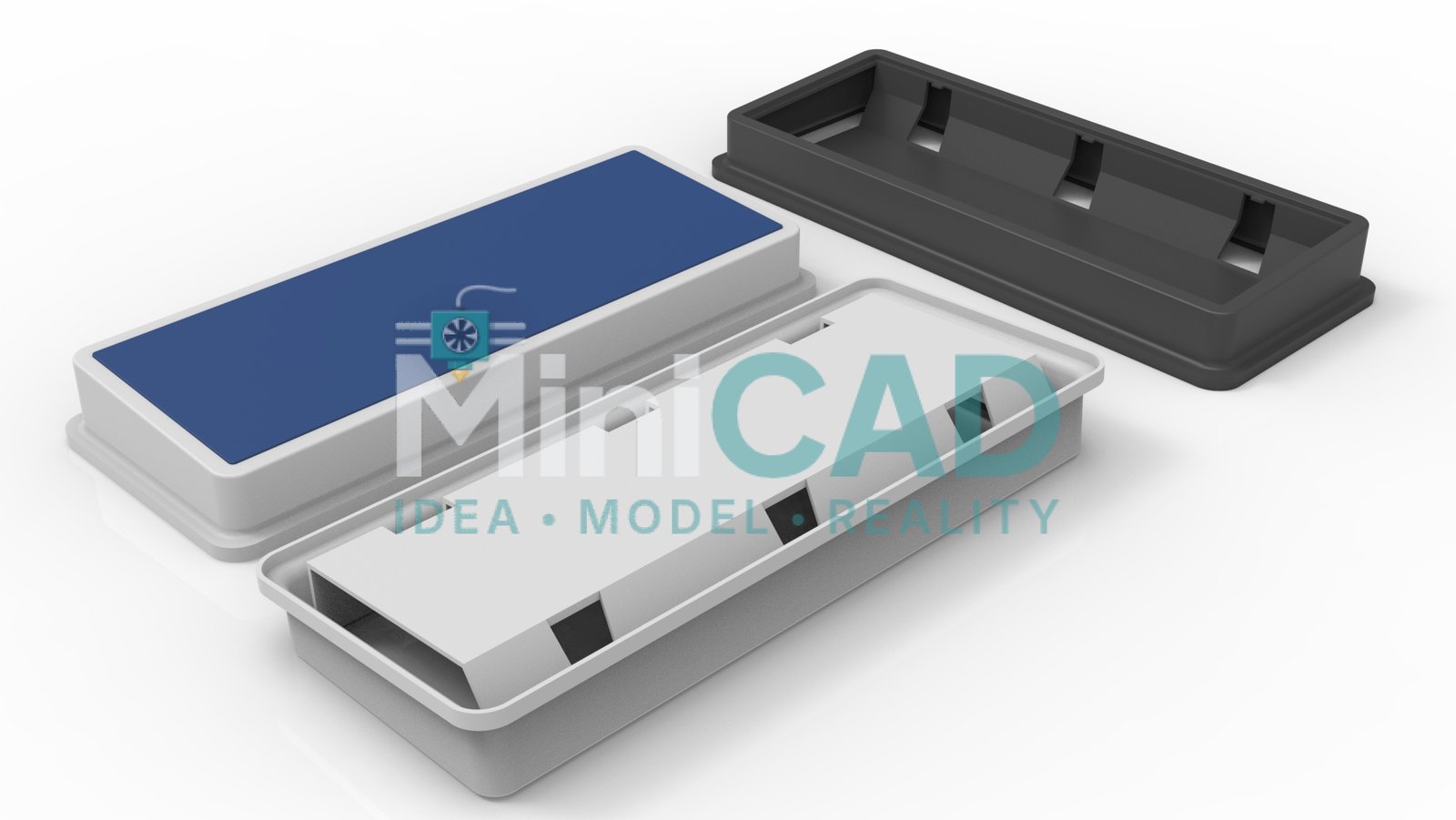
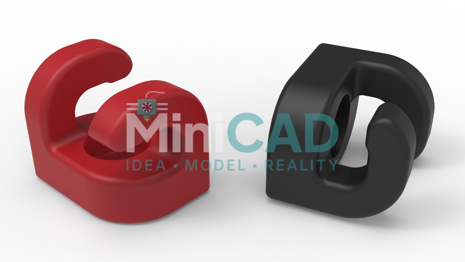
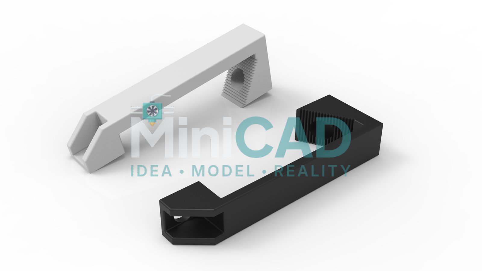
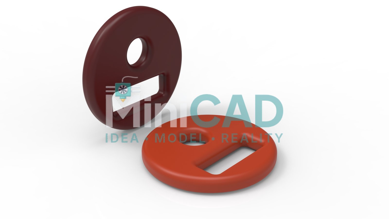
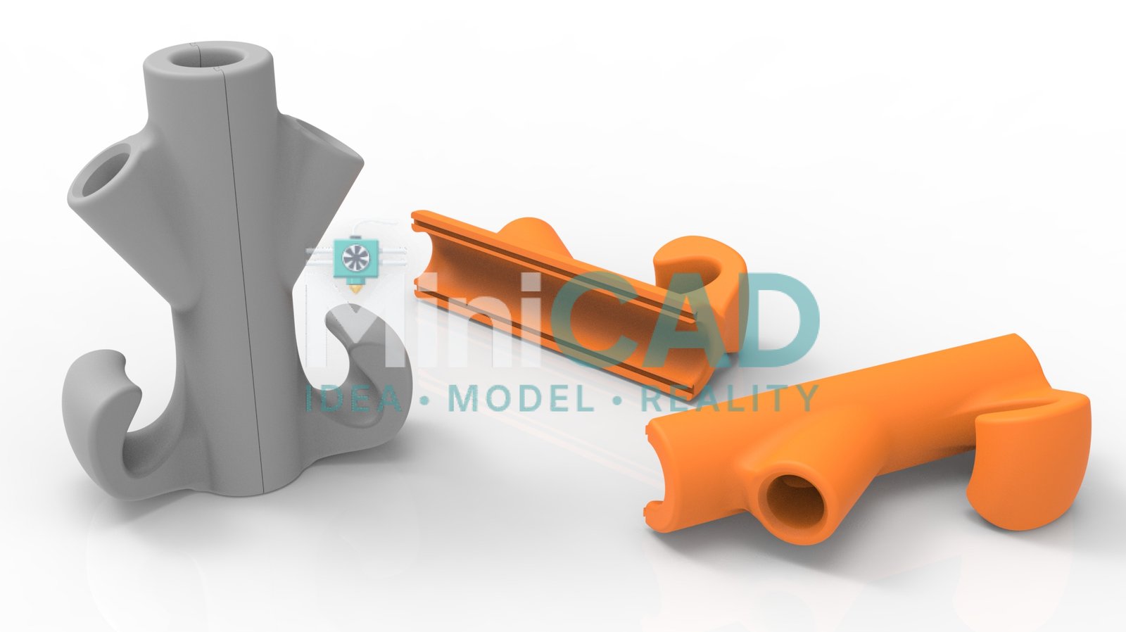
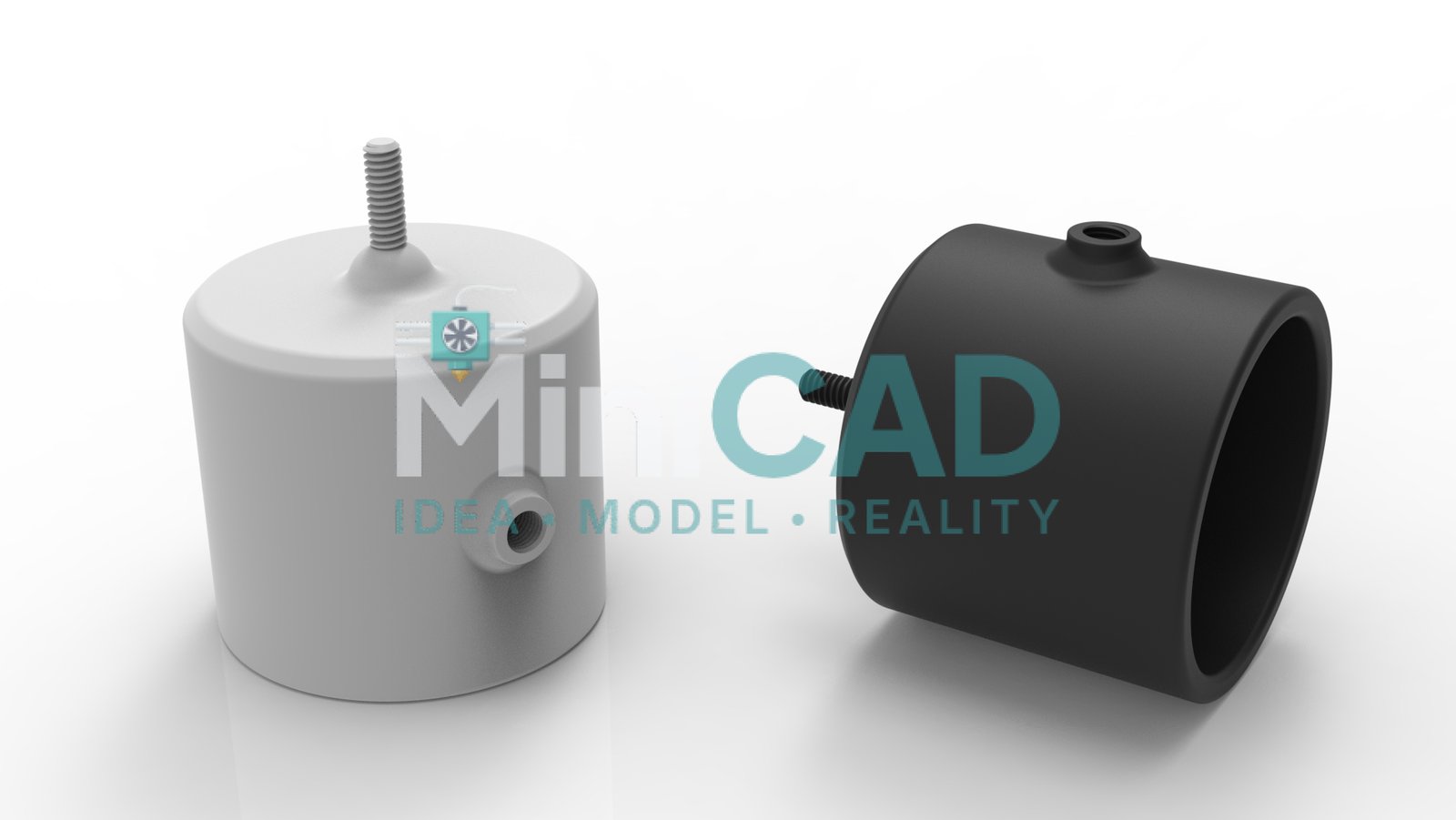
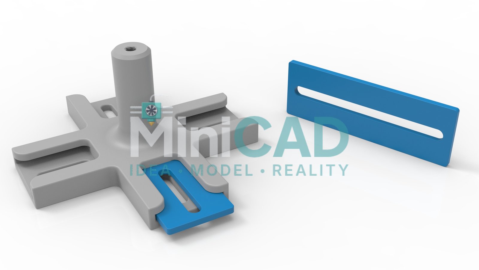
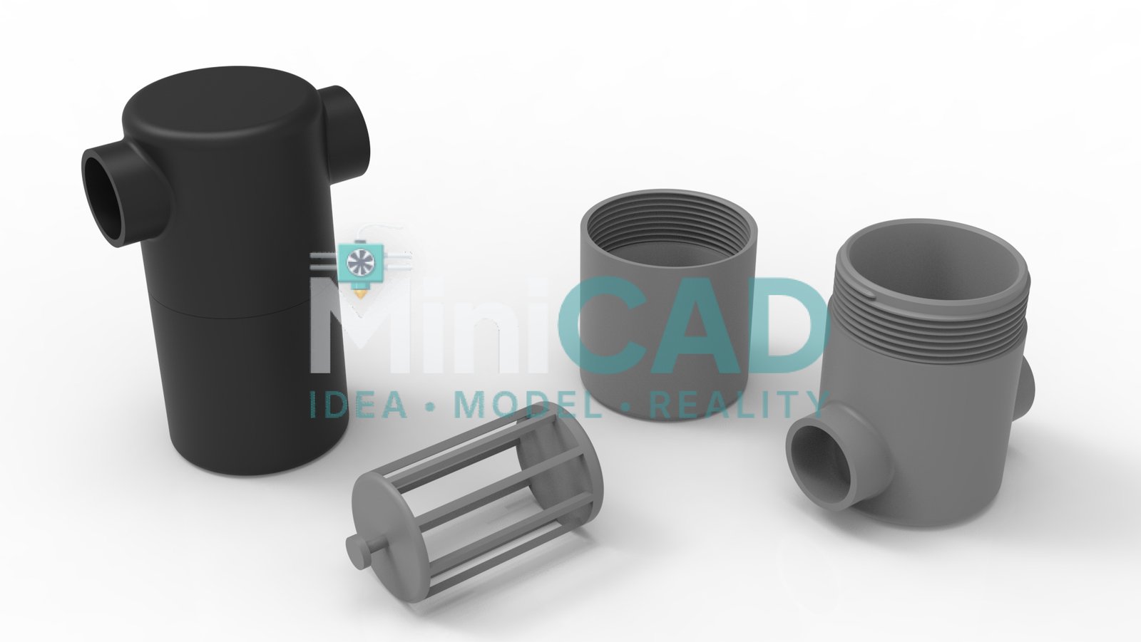
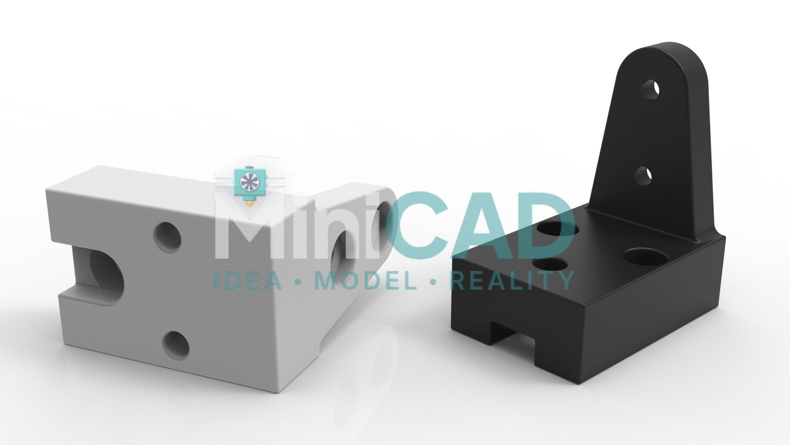
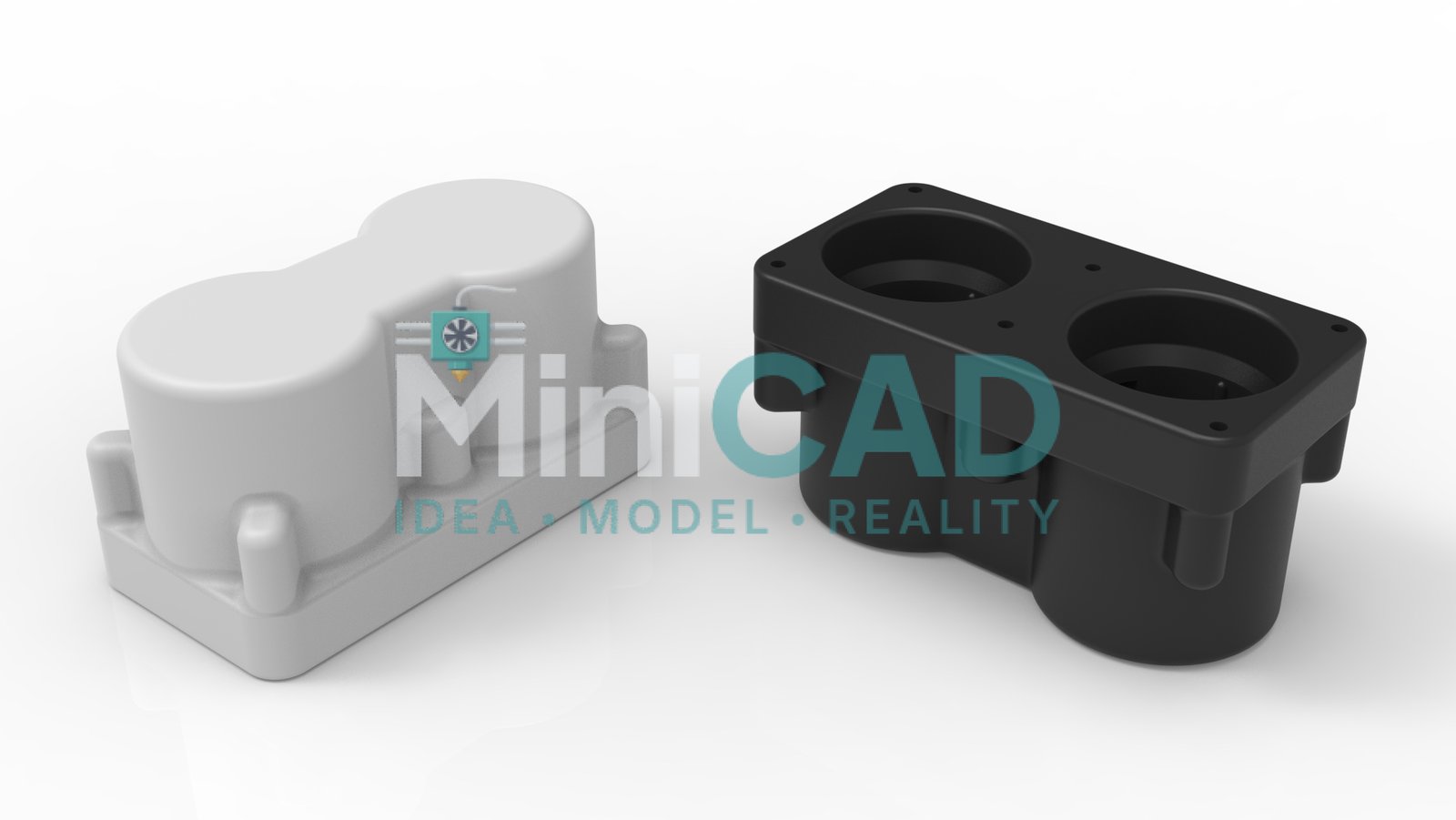
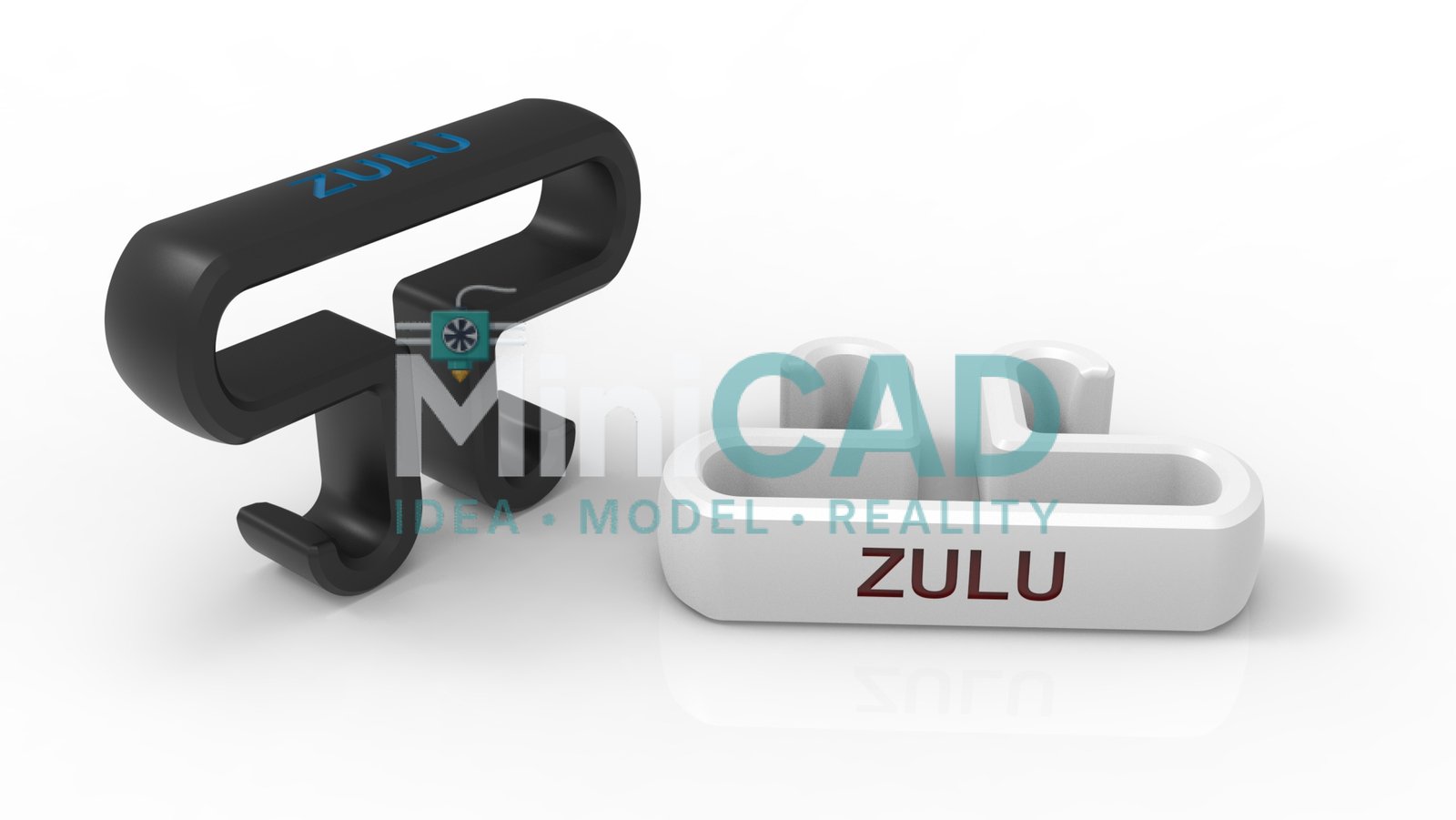
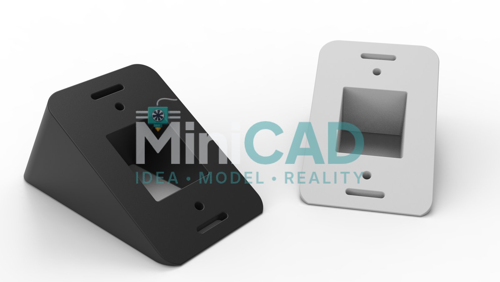
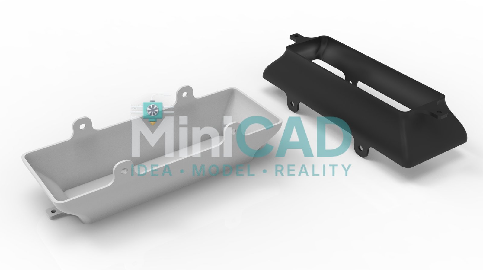
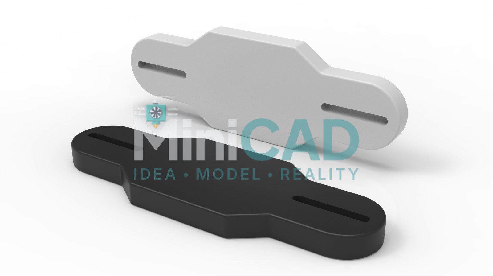
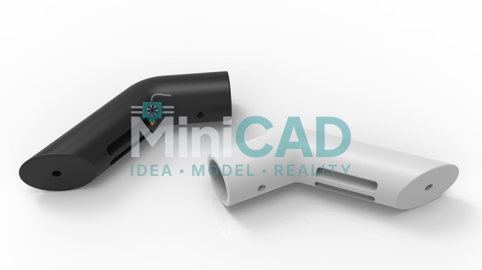
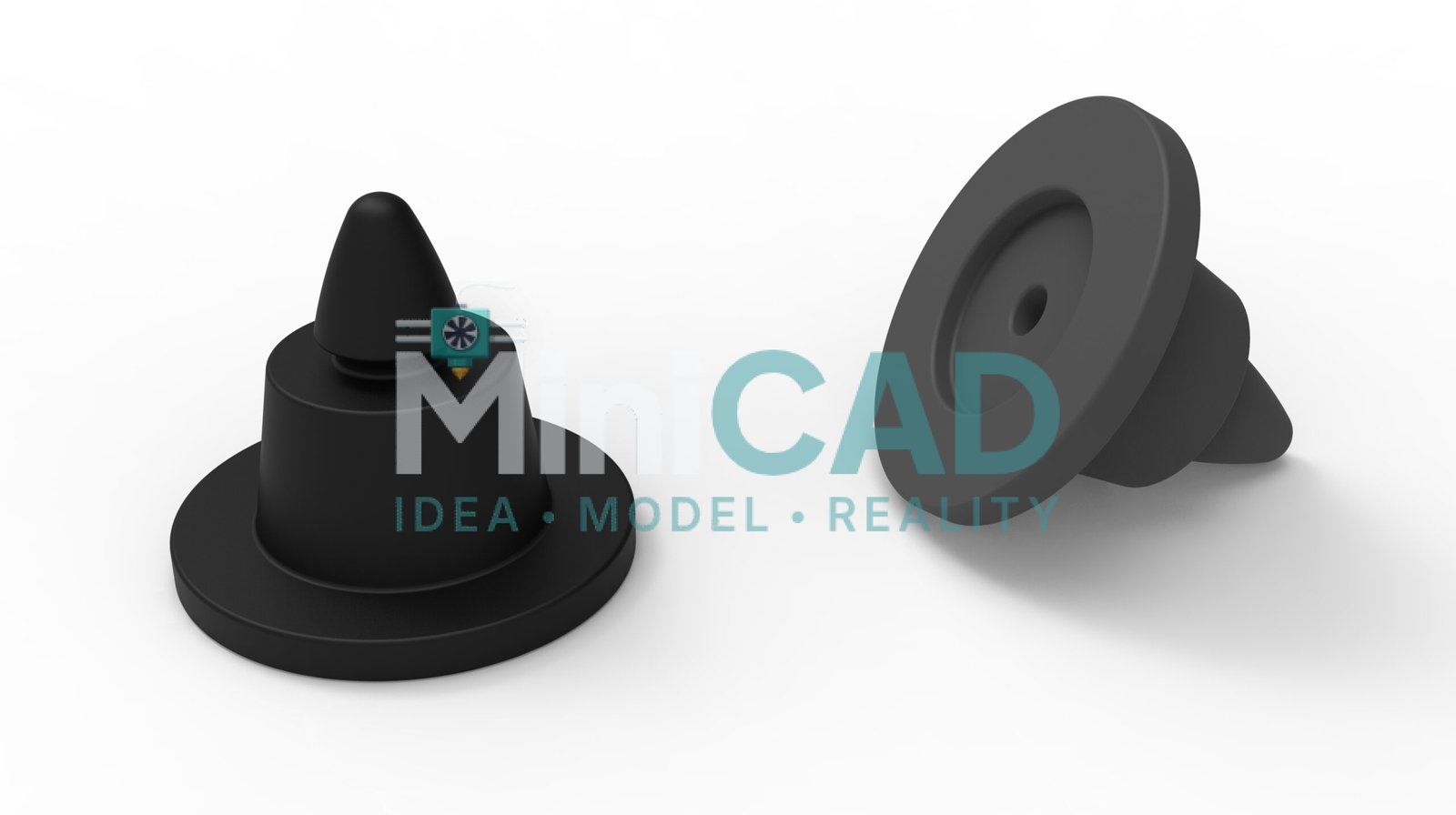
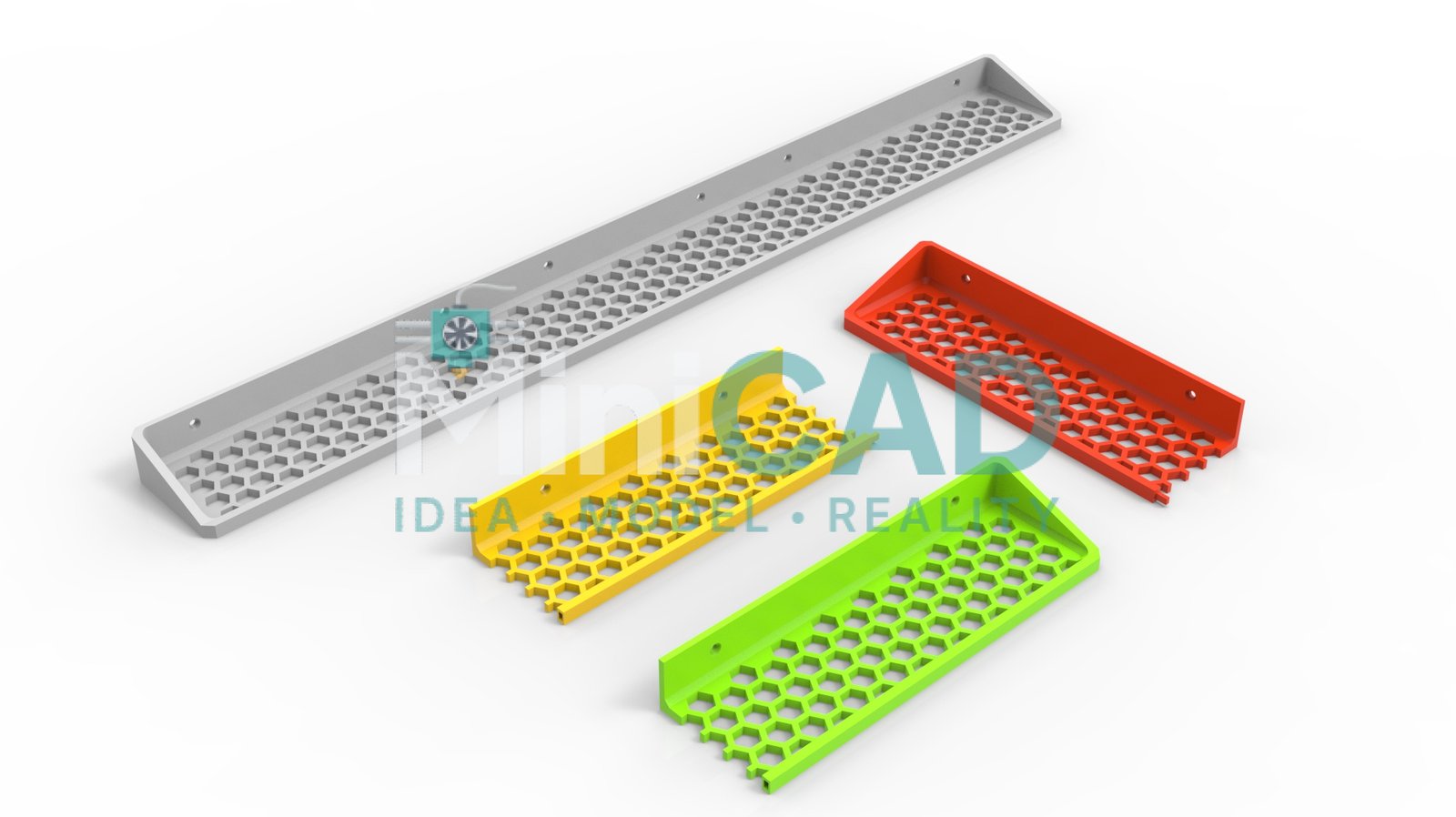
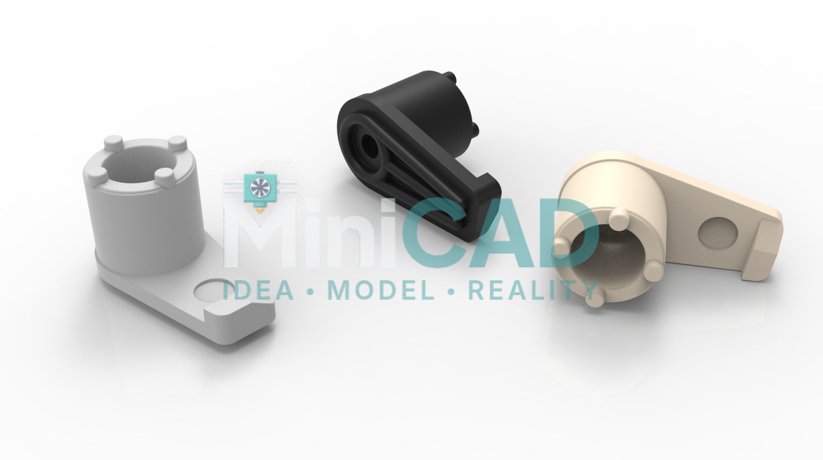
The client needed a series of custom mounting brackets for a robotics and electronics installation — wall mounts, sensor holders, and pipe clamps — none of which matched any off-the-shelf solution. Each bracket had to align with existing hardware at specific bolt patterns and clearance distances. Our solidworks modeling service handled every part in a single order: modeled, toleranced, and exported in three formats.
SolidWorks Modeling Approach
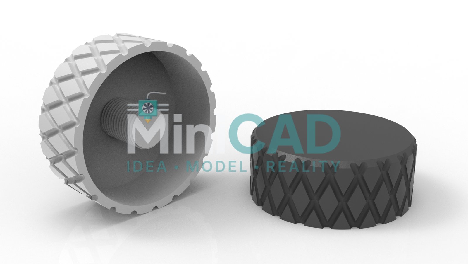
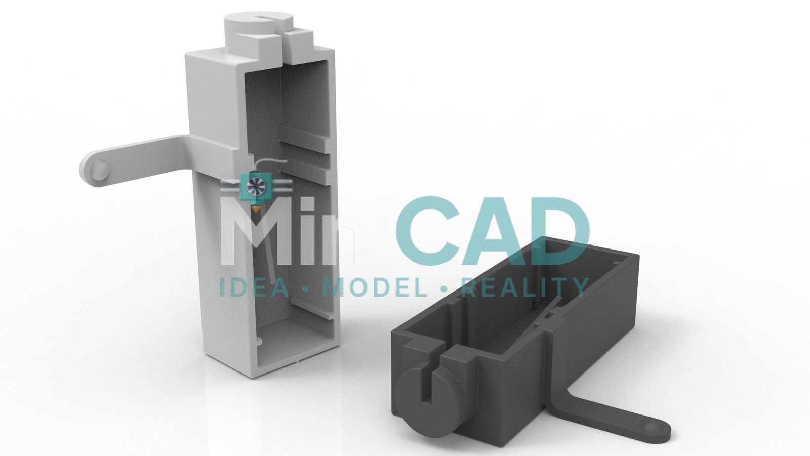
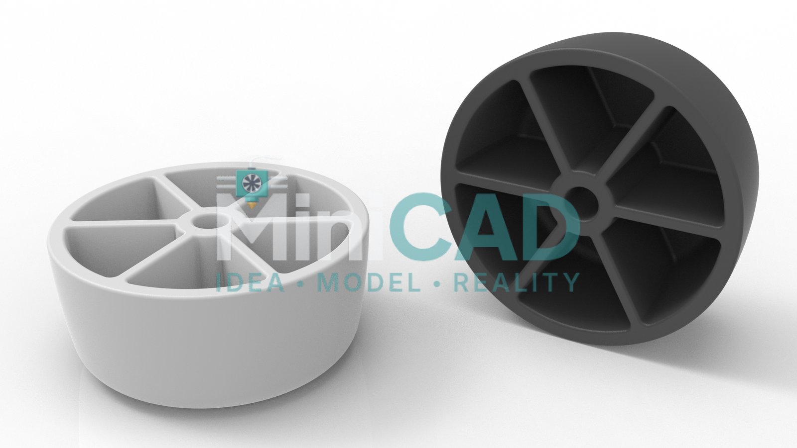
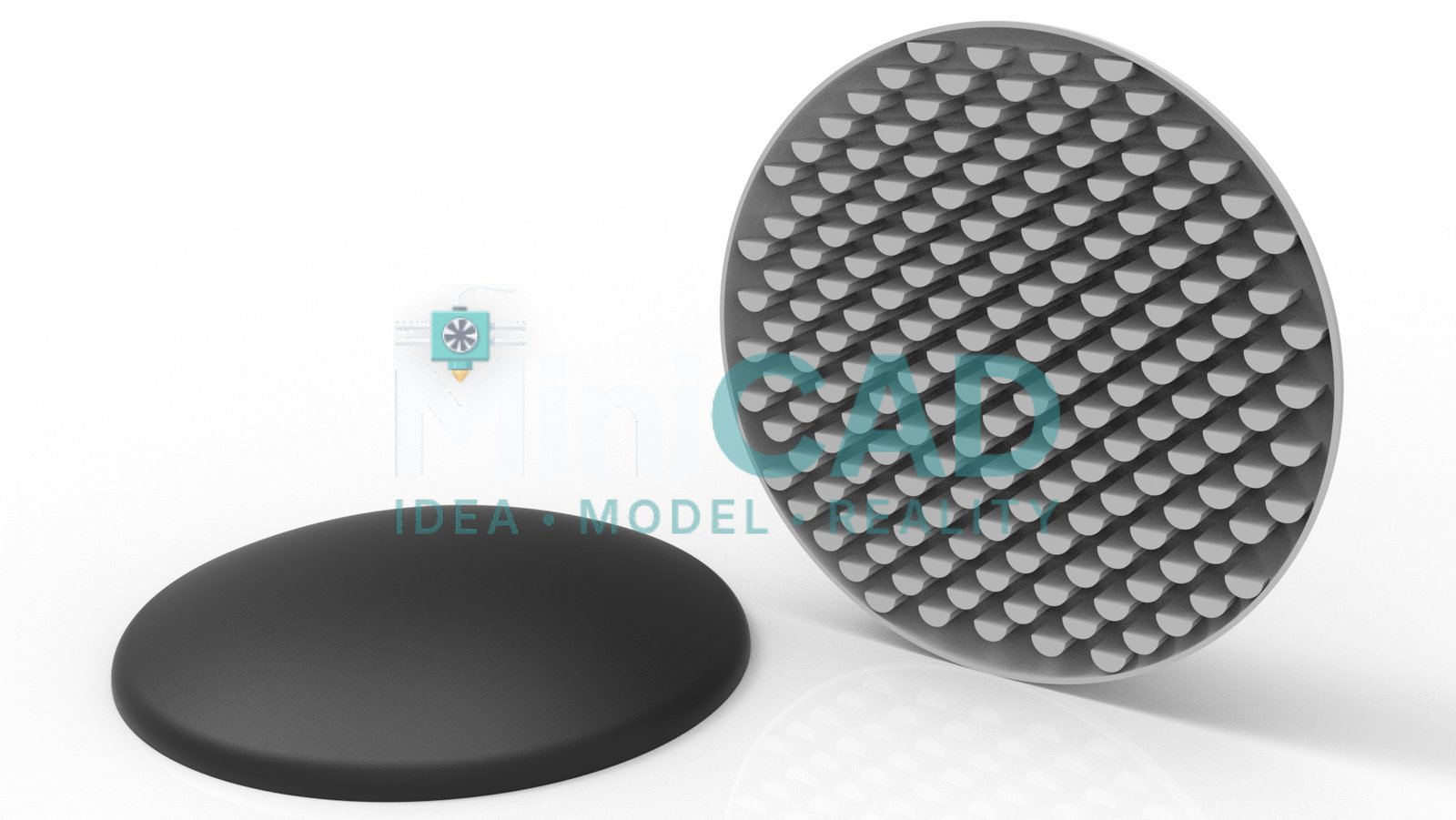
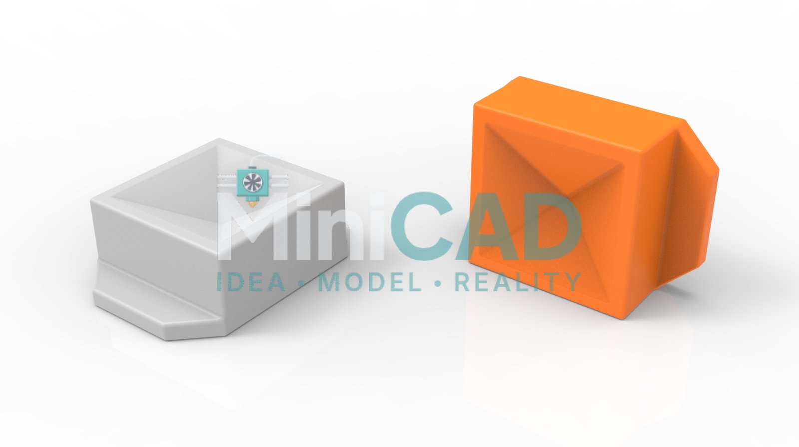
Every bracket was built as a fully parametric SolidWorks part with a clean feature tree. Sketch constraints captured design intent — horizontal and vertical relations, symmetric mates, collinear edges — so that dimension changes propagated correctly through every downstream feature. For cad design for 3d printing, we validated wall thickness at every cross-section (minimum 1.6mm for FDM) and oriented features to minimize support material. The STEP export was verified in a neutral viewer before delivery.
File Deliverables
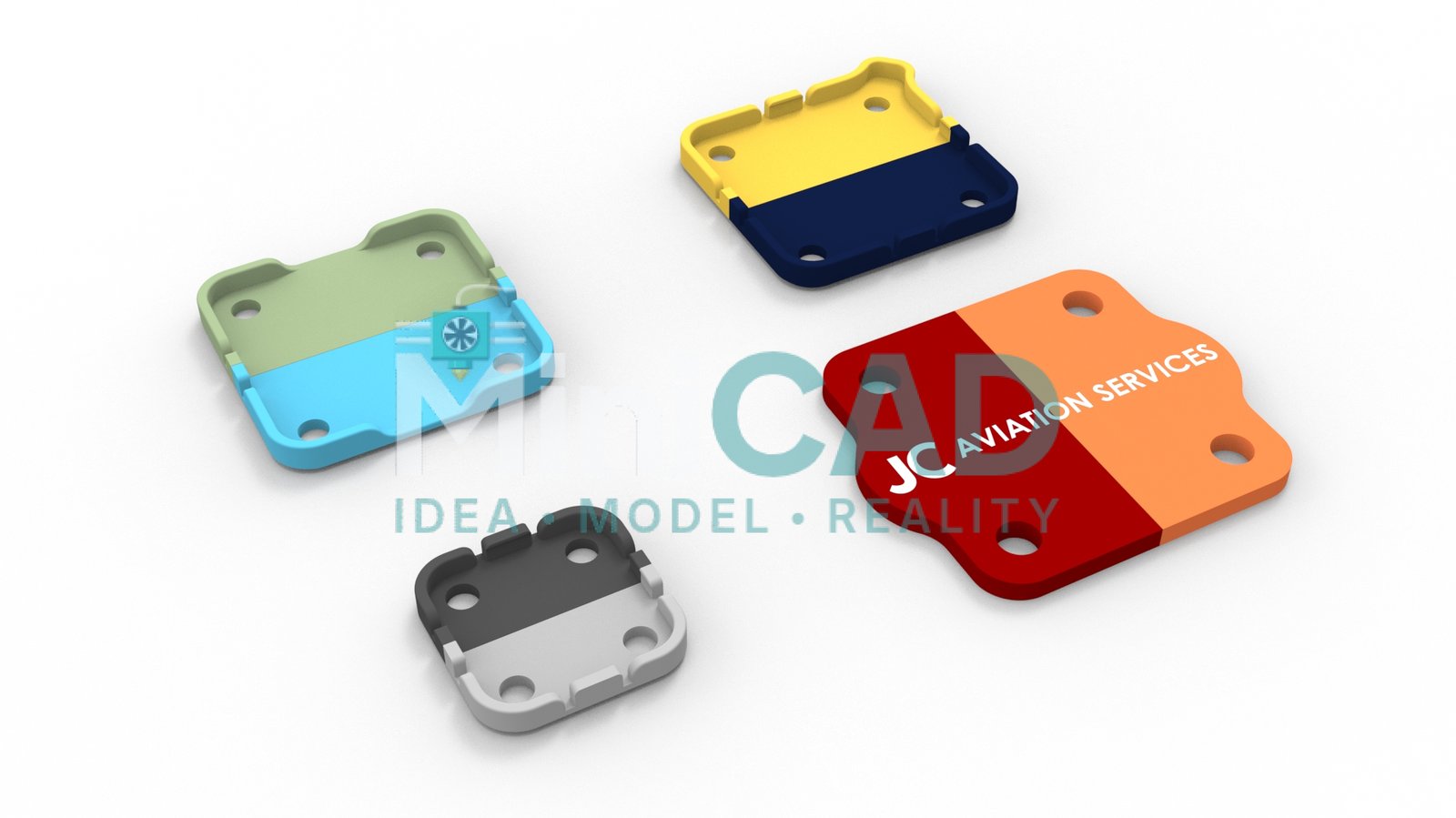
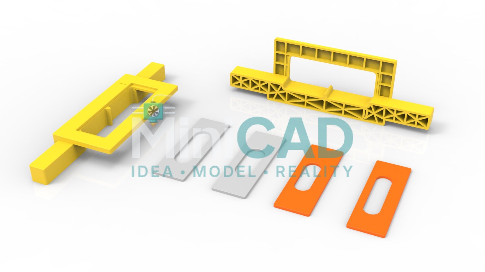
Three file formats were delivered for each bracket. STL binary for direct slicing on any FDM printer. 3MF preserving full print settings including layer height, infill, and support configuration. STEP AP214 for any custom cad design service downstream work — CNC machining, injection molding quoting, or design modification by the client’s own engineer. All files passed manifold validation before export.

Materials and Applications
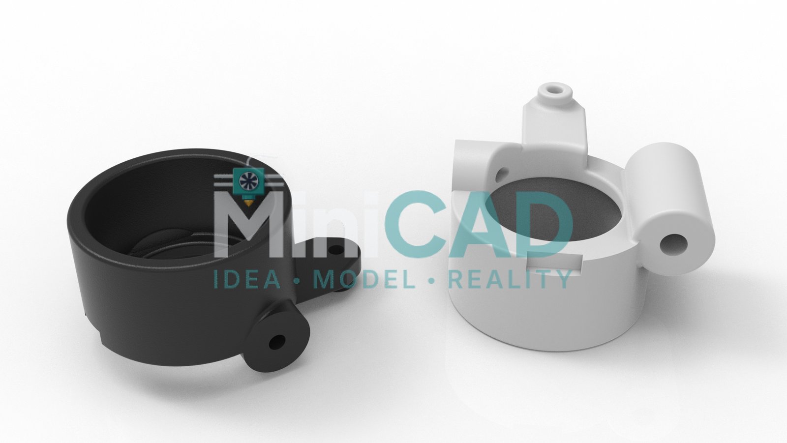
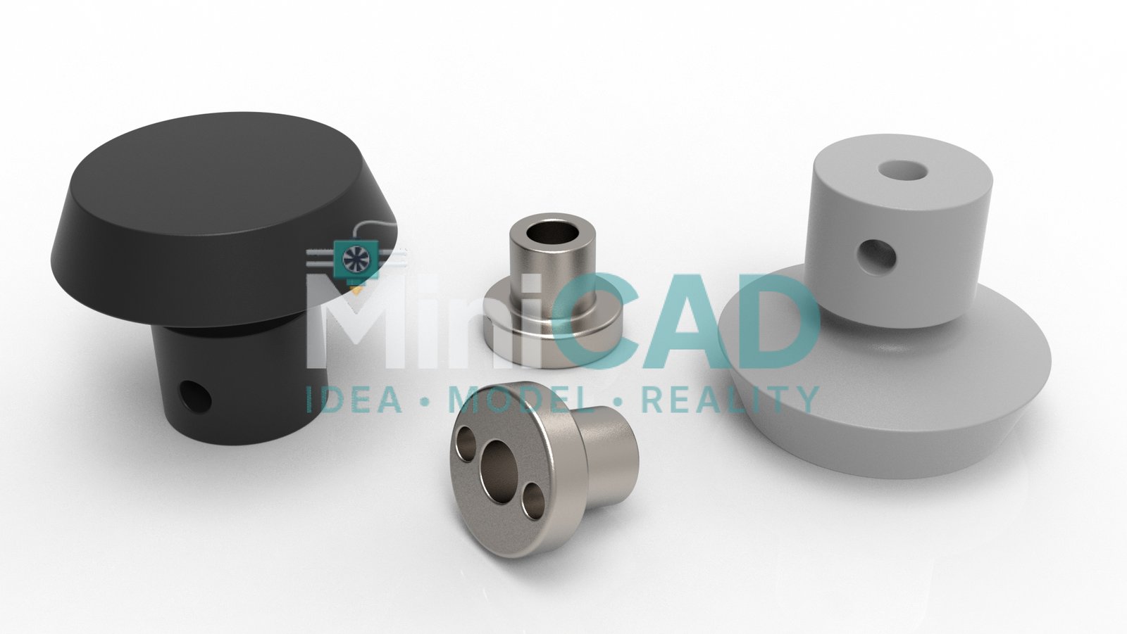
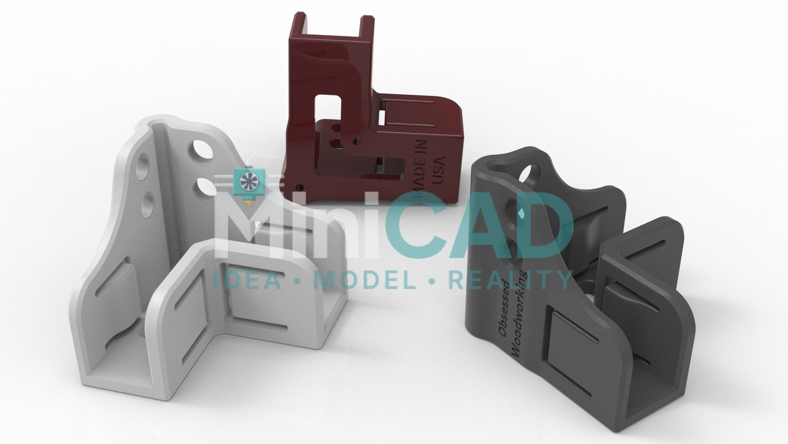
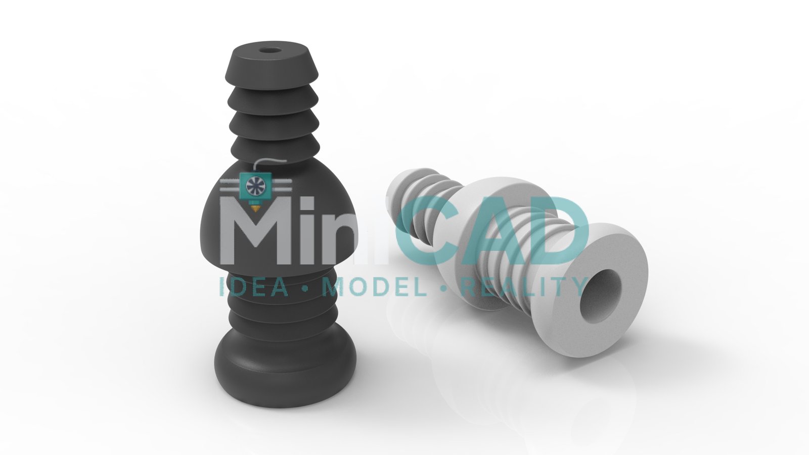
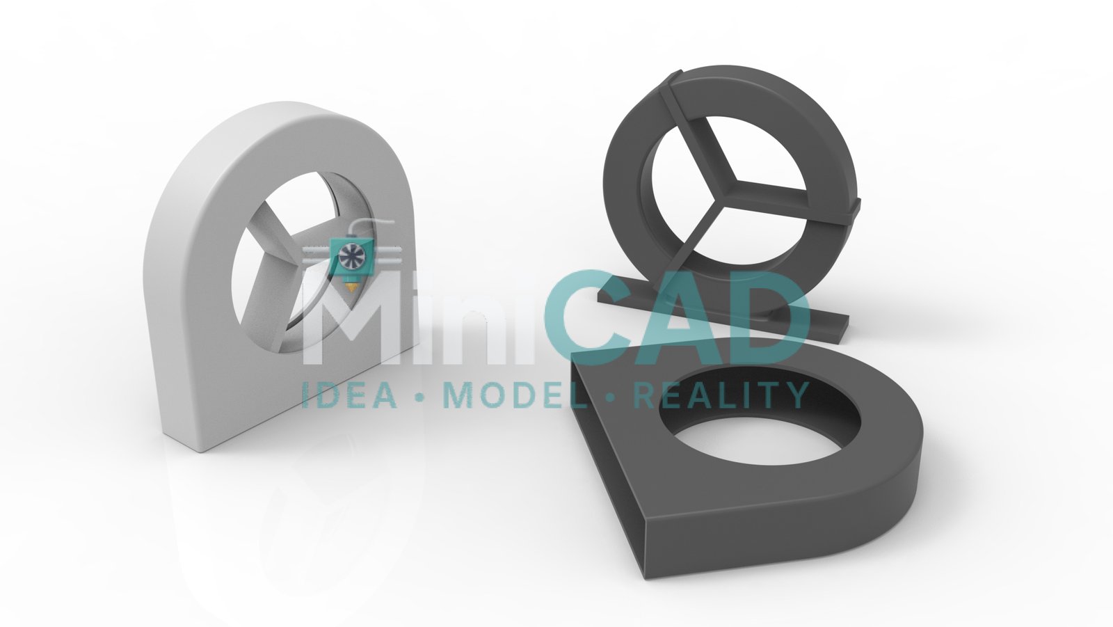
The print geometry was designed to work in PLA for lightweight indoor use and PETG for applications requiring mild chemical resistance or outdoor exposure. Wall thickness and infill zones were specified per bracket type — structural mounting brackets at 40% gyroid infill, lightweight sensor holders at 20% grid. The 3d model for manufacturing STEP file was simultaneously quoted by a CNC aluminium vendor for a higher-strength variant of the main wall mount.
Delivery and Turnaround
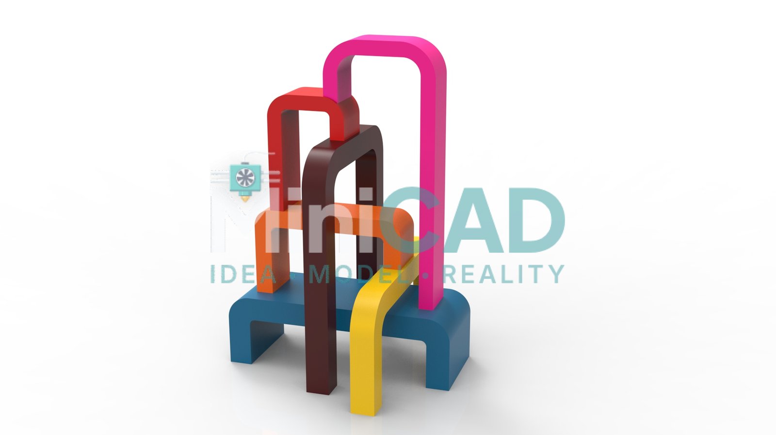
All seven brackets in this project were delivered within 24 hours of brief confirmation — a standard outcome for our reverse engineering and CAD replication service. If you have an existing part with no CAD file, or a hardware requirement that no standard bracket addresses, we build it from your measurements. Start your order at Order or review pricing at Pricing.
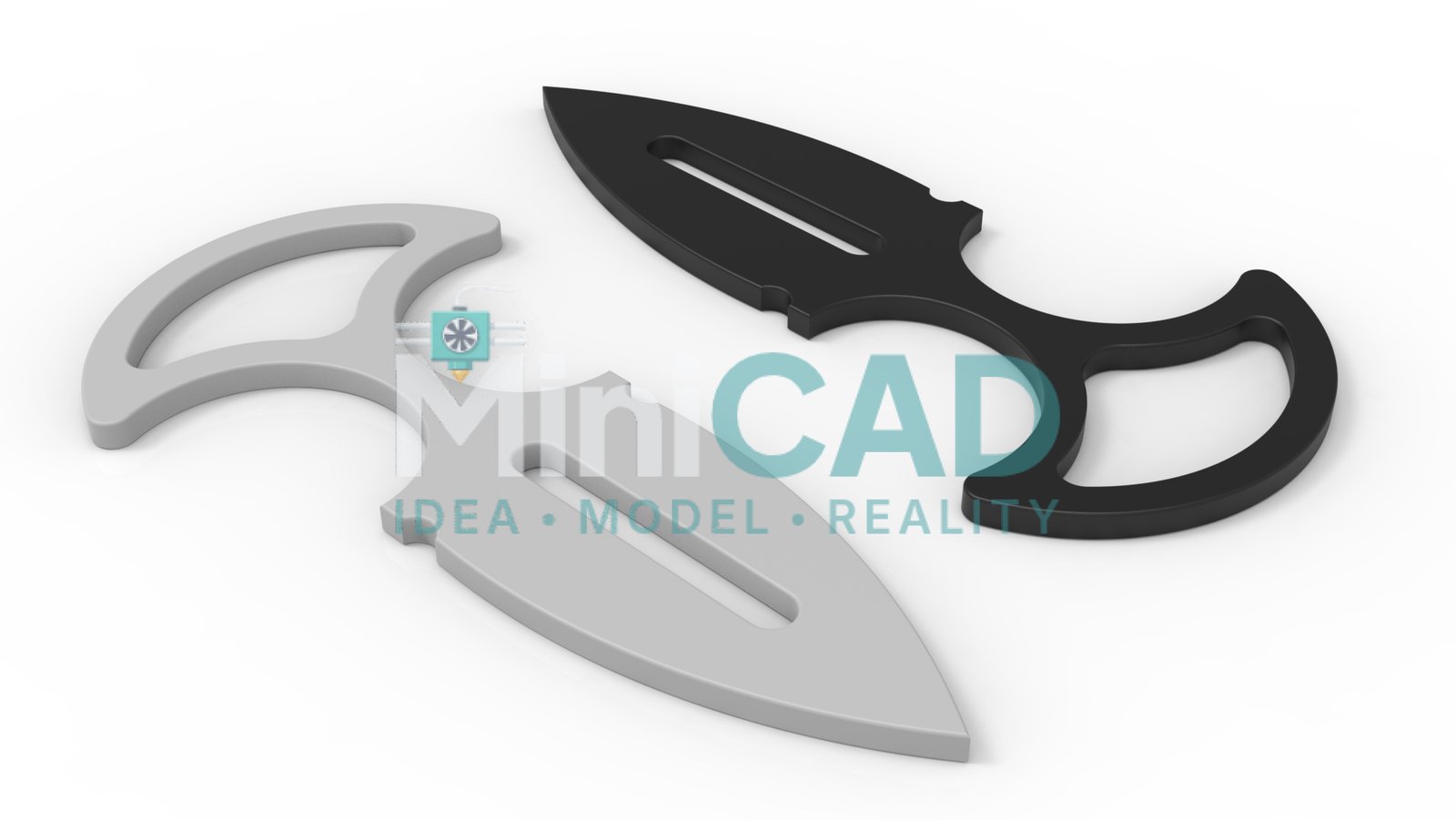
Why Outsource CAD Design Rather Than Use a Template
Off-the-shelf brackets cover standard applications — VESA mounts, DIN rail clips, pipe saddles. The moment your hardware deviates from a standard bolt pattern, tube diameter, or clearance requirement, a template becomes a starting point for iteration rather than a solution. When you outsource cad design to an engineer who models from your actual caliper measurements, the result fits on the first print. This project required seven distinct bracket geometries — none existed in any standard catalog. Every one was built parametrically in SolidWorks so dimension changes propagated correctly to related features without rebuilding. The 3d model for manufacturing STEP file was simultaneously sent to a CNC aluminium vendor for a higher-strength variant of the main wall mount, and it passed the vendor’s drawing review on first submission without a revision request. That is the structural advantage of a purpose-built custom cad design service over a modified template: the model carries engineering design intent at every feature — sketch relations, tolerance selections, and material specification — not just surface geometry.

